Download
1 / 15
160 likes | 328 Views
The construction of the model of the curved fast ramped superconducting dipole for FAIR SIS300 synchrotron. P.Fabbricatore 1 , F. Alessandria 2 , G. Bellomo 2 , S. Farinon 1 , U. Gambardella 3 , R.Marabotto 4 , R.Musenich 1 , M. Sorbi 2 , and G. Volpini 2 ( 1) INFN-Genova, Italy

E N D
The construction of the model of the curved fast ramped superconducting dipole for FAIR SIS300 synchrotron P.Fabbricatore1, F. Alessandria2, G. Bellomo2, S. Farinon1, U. Gambardella3 , R.Marabotto4, R.Musenich1, M. Sorbi2, and G. Volpini2 (1)INFN-Genova, Italy (2)INFN-LASA and Milan University, Physics Department, Italy (3)INFN-Laboratori di Frascati, Italy (4)ASG-Superconductors (former Ansaldo Superconduttori), Genova, Italy The aim of this talk is to give some interesting information related to the construction of a curve cos-theta dipole magnet employing a conductor optimized for low ac losses
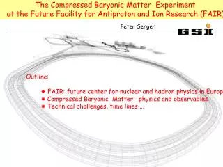
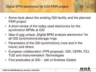
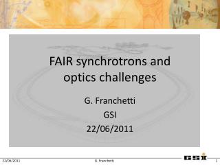
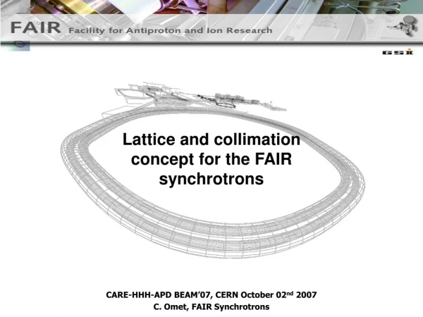
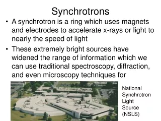
The facility FAIR including the synchrotrons SIS100 and SIS300 • The SIS300 will be installed on top of SIS100 in the same tunnel. • The maximum magnetic rigidity is 300 Tm • Curved super conducting cos(θ)-type magnets will be used with a maximum field of 4.5 T in the dipoles, to be ramped at 1T/s : 48 long (7.757 m) 12 short (3.879 m) dipoles
Criticities of SIS300 dipoles leading to manufacture difficulties Ramp 1T/s ac losses Premature Quench Costs of Cryogenics Hence: Development of a low loss conductor Design with loss minimization (taking care of eddy currents) Low ac losses Cored conductor Constructive problems Curvature R=66.667 m (sagitta 117 mm ) Constructive problems 107 cycles Fatigue Mechanical design and materials optimization
Basic assumptions and consequences • Our starting assumption was that the coil should be curved since the winding, rather than bending a straight coil because: • This solutions allows defining without uncertainty the geometrical dimensions of a curved stress-free coil; • Once cured, the coil can be handled in simple and safe way for the following manufacturing operations (collaring, insertion in the iron yoke, …). • Curved winding single layer coilmechanically supported only by the collars (mechanical coupling between two curved layers or between a curved collared coil and a curved yoke appeared to be critical operations)
Winding operations: Curved mandrel and mold, curved winding of a cored cable See poster 4MPB-05 G.Volpini
Some winding details Only the external side of the coil ends is impregnated. The turns at the inner side shall be into direct contact with coolant
Coil dimensions After curing the poles were places under a calibrated pressing device, able to give the differences of the azimuthal dimension with respect to the nominal one at 50 MPa.
A suitable polar shim is applied for having the planned pre-stress level
Collaring The collars are plates 2.8 mm thick, made of high strength austenitic steel developed by Buderus Edelstahlexpressly for this project. The alloy is characterized by a high content of manganese and nickel (11.5%) and has a high elastic limit; the yield stress is 650 MPa at RT and 1800 MPa at 4.2K; the tensile stress is 860 MPa at RT and more than 1900 MPa at 4.2K. The elongationat 4.2K is 23% and the magnetic permeability 1.0019
Some problems with collaring operation Surprisingly the pressure to be applied, for aligning the holes hosting the keys at the mid-plane, resulted 30% lower than nominal. This phenomenon has not yet completely clarified; we believe that the dimensions of the coil under pressure, as measured using the calibrated pressing device (400 mm long) are not correct. Many possible reasons under investigation. The coil was un-collared and re-collared with a 0.3 mm thicker shim
Integration into the iron yoke Long and difficult construction of the yoke assembling 3568 steel plates 1 mm thick in four curved blocks and 426 stainless steel plates in two smaller blocks for the coil end . Excellent fitting of the curved collared coil into the curved yoke.
How the magnet presently appears and steps to completion The magnet is ready to be enclosed into the external shell. The main body of the shell is a curved cylinder, composed of two stainless steel AISI316L halves to be coupled to the magnet and welded at the mid-plane. The shell is 10 mm thick. At room temperature, it is not pressed around the magnet structure but only coupled with a calibrated small gap between shell and magnet. Once cooled down to 4.2 K, due to the differential thermal contraction a soft contact should raise at the interface shell-iron yoke
CONCLUSIONS A curved superconducting dipole cos-theta for SIS 300 has been developed and it is now close to construction completion. Many constructive problems to be faced and mainly coming from the geometrical curvature, which also had forced specific design choices: one layer, strength provided by collars only, mid-plane gap in iron yoke, longitudinal pre-stress achieved after cool-down (See poster 5LPG-05 S.Farinon). The magnet will be tested in vertical at INFN LASA in Milan this autumn (See poster 5LPG-06 M.Sorbi) . The results of this test would, hopefully, confirm the design choices and constructive methods.