Designing Space for Safe, Reliable & Efficient Combustion Processes
280 likes | 327 Views
Learn about combustion stability, geometry selection, and design considerations for combustors. Understand combustion zone sizing, pressure drop, heat release rates, and more.

Designing Space for Safe, Reliable & Efficient Combustion Processes
E N D
Presentation Transcript
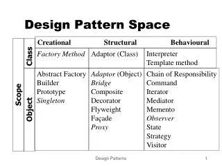
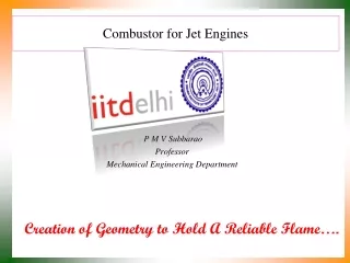
Design Space for Combustor P M V Subbarao Professor Mechanical Engineering Department Selection of Geometry to Proved Safe, Reliable & Efficienct Combustion ….
Simple Bunsen Burner Burning Velocity Flow velocity Air Fuel
Stability & Flammability Limits • Burning Velocity > Flow Velocity : Flash Back Limit • Burning Velocity < flow Velocity : Blow Off Limit • Burning Velocity = Flow Velocity : Stable Flame. Rich Mixture Fuel Flow rate Flash Back Stable Flame Blow off Lean Mixture Air Flow rate
Design Constraints: Flow Velocity Region of Stable Burning
Flash Point Design Constraints: Mixture Temperature Saturation Line Rich Mixture Flammable mist Spontaneous Ignition Flammable Vapour Lean Mixture SIT of Aviation fuels: 501 – 515 K Mixture Temperature
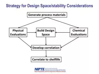
Macro Design Parameter for Combustor • The ability of the combustion process to sustain itself in a continuous manner is called Combustion Stability. • Stable and efficient combustion can be upset by too lean or too rich mixture. • This situation causes blowout of the combustion process. • The effect of mass flow rate, combustion volume and pressure on the stability of the combustion process are combined into the Combustor Loading Parameter (CLP), defined as • n ~ 1.8
Combustion Stability Characteristics Unstable Stable Unstable CLP
Combustion Design Considerations • Cross Sectional Area: The combustor cross section is determined by a reference velocity appropriate for the particular turbine. • Another basis for selecting a combustor cross section comes from thermal loading for unit cross section. • Length: Combustor length must be sufficient to provide for flame stabilization. • The typical value of the length – to – diameter ratio for liner ranges from three to six. • Ratios for casing ranges from two – to – four. • Wobbe Index: This is an indicator of the fuel characteristics and stability of the combustion process.
Design Constraints • Pressure Drop: The minimum pressure drop alllowed is upto 4%. • Volumetric Heat Release Rate: The heat-release rate is proportional to combustion pressure. • Actual space required for combustion varies with pressure to the 1.8 power.
Length Scaling • An estimate of the size of main burner is required during the engines preliminary design. • The cross sectional area can be easily determined using velocity constraints. • The length calculations require scaling laws. • The length of a main burner is primarily based on the distance required for combustion to come to near completion. • Residence time tres in main burner is given by
Design Steps: Combustor Residence time The reaction time is inversely proportional to the reaction rate and the reaction rate is directly proportional to initial total pressure.
Total Pressure Loss in Turbo Combustor The loss of pressure in combustor (p0,ex <p0,in) is a major problem. The total pressure loss is usually in the range of 2 – 8% of p0,in. The pressure loss leads to decrease in efficiency and power output. This in turn affects the size and weight of the engine. There are several methods of quantifying the total pressure loss in a combustor, Relative to the total inlet pressure: Relative to the inlet Dynamic pressure: Relative to a reference dynamic pressure:
Development of differential Equation for Axial Evolution of Mach Number Divide throughout by dx Multiply throughout by M2
Differential Equation for Axial Evolution of Mach Number For a uniform wall heat flux q’’
Selection of Combustor Inlet Mach Number • Air from the engine compressor enters the combustor at a velocity of about 150 m/s, which is far too high for sustained combustion to take place. • The air is first decelerated to a velocity of about 25 m/s in a pre-diffuser. • The speed of burning kerosene at normal fuel-air ratios is only about 5-10 meters per second; hence any fuel lit even in the prediffused air stream also would be blown away. • Therefore, a region of low axial velocity is created in the combustor, through swirlers so that the flame will remain alight throughout the range of engine operating conditions.