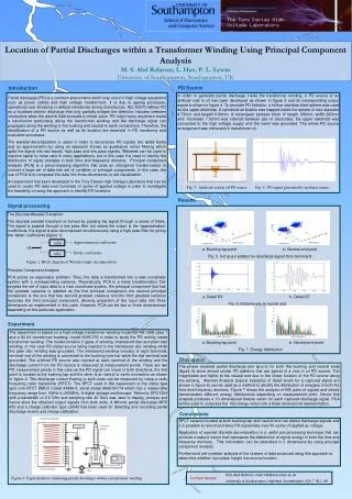
Weighted Adaptive Lifting-based Wavelet Transform
Weighted Adaptive Lifting-based Wavelet Transform. Yu Liu and King Ngi Ngan Department of Electronic Engineering The Chinese University of Hong Kong ICIP 2007, San Antonio, Texas, USA, Sept. 16-19, 2007. 1. Outline. Introduction Background and Problem Statement

Weighted Adaptive Lifting-based Wavelet Transform
E N D
Presentation Transcript
Weighted Adaptive Lifting-based Wavelet Transform Yu Liu and King Ngi Ngan Department of Electronic Engineering The Chinese University of Hong Kong ICIP 2007, San Antonio, Texas, USA, Sept. 16-19, 2007 1
Outline • Introduction • Background and Problem Statement • Weighted Adaptive Lifting-based Wavelet Transform • Experimental Results • Conclusion 2
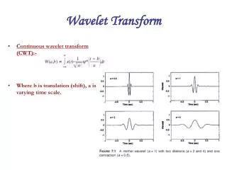
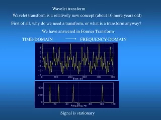
Introduction Discrete Wavelet Transform (DWT) Multi-resolution representation Energy compaction and decorrelation Wavelet-based JPEG2000 V.S. DCT-based JPEG 2D-DWT with directionally spatial prediction Natural images often contain richly directional attributes such as linear edges, in neither horizontal nor vertical direction 2D transform involves two separable 1D transform Separable 1D horizontal/vertical transform Large magnitude in those high-frequency coefficients of edges Lifting S cheme An efficient implementation of DWT with low memory and computational complexity
Background (1) Conventional Lifting Scheme [Sweldens96] A typical lifting stage is comprised of four steps: Split: xe[n] and xo[n] Predict: Update: Normalize:ke and ko Fig.1 The lifting scheme, (a) Forward transform, (b) Inverse transform
Background (2) Adaptive Directional Lifting Scheme [Ding2007] Direction Aligned Lifting Operator P and U Direction Aligned Predict (DAP) Direction Aligned Update (DAU) Fig. 2. The directional lifting scheme, (a) Forward transform, (b) Inverse transform
Background (3) Adaptive Directional Lifting Scheme A 2D transform involves two separable transform Separable horizontal/vertical lifting-based transform Predict with an optimal direction Update with the inverse direction Sub-pixel interpolation Sinc Interpolation is always performed in horizontal/vertical direction The prediction and update processes with vertical angle in separable vertical transform, where integer pixels are marked by “o”, half pixels by “+” and quarter pixels by “x”
Problem Statement Different Lifting Schemes Problems existing in ADL Scheme Mismatch between predict and update step Interpolation favoring only horizontal/vertical direction Invariant interpolation filter coefficients for all images (a) Conventional Lifting, (b) Adaptive Directional Lifting (ADL), (c) Weighted Adaptive Lifting (WAL)
Weighted Adaptive Lifting-based Wavelet Transform (1) • Weighted Function • Weighted functions for directional prediction • (1) • Integer Pixel precision: • Fractional Pixel precision: where is the coefficient factor of the interpolation filter. The weighted functions for directional prediction, (a) (b) (c). Integer pixel precision, (d) (e) Fractional pixel precision
Weighted Adaptive Lifting-based Wavelet Transform (2) • Weighted Lifting Scheme • High-pass coefficient is obtained by • (2) • wherewk is the weighted parameter. • Low-pass coefficient is calculated by • (3) • It means that the high-pass coefficient will be added exactly to the pixels they are predicted.
Weighted Adaptive Lifting-based Wavelet Transform (3) • Directional Interpolation Fig. 5. Directional Interpolation Filter
Weighted Adaptive Lifting-based Wavelet Transform (4) • Directional Interpolation • Construction of directional interpolation filter • bilinear filter • Telenor 4-tap filter: • ¼: (-1,13,5,-1)/16 • ½: (-2,10,10,-2)/16 • ¾: (-1,5,13,-1)/16 • 2-tap filter: (-1,5)/4 TABLE I: Directional Interpolation Filter
Weighted Adaptive Lifting-based Wavelet Transform (5) • Adaptive Interpolation Filter • To minimize the energy of the high subband • The minimization problem • can be solved by the Wiener-Hopf equation
Weighted Adaptive Lifting-based Wavelet Transform (6) • Side Information • Ideally, one optimal direction would be assigned to each pixel. • But, to reduce the bits for coding the direction information, a tree-structured macroblock-partition scheme is employed, like H.264/AVC • To find the best direction vector, minimize the Lagrangian cost function: • To find the best mode type, minimize the Lagrangian cost function: • To decide whether the calculated optimal filter or the default filter is adopted, minimize the Lagrangian cost function:
Weighted Adaptive Lifting-based Wavelet Transform (7) • Side Information • Mode type coding • encoded by UVLC (universal variable length coding) • Direction vector coding • only the differences between direction vectors and their predictors from the neighboring blocks are encoded • Adaptive interpolation filter coefficients coding • since the coefficients are transmitted once per image, the additional bits for the coefficients are negligible
Experimental Results for Image Coding (1) TABLE: Comparison of coding performance (in dB) of different lifting schemes with 5/3-tap biorthogonal filter and three decomposition levels
Experimental Results for Image Coding (2) Fig. 6 Part of the decoded Barbara images at rate 0.25bpp (a) Original Barbara, (b)decoded Barbara by J2K (27.38 dB), (c) decoded Barbara by WAL (30.40dB)
Experimental Results for Image Coding (3) Fig. 7 Part of the decoded Foreman images at rate 0.25bpp (a) Original Foreman, (b)Decoded Foreman by J2K (32.32dB), (c) Decoded Foreman by WAL (33.78dB)
Conclusion Weighted Adaptive Lifting (WAL)-based Wavelet Transform for Image Coding Weighted Function Directional Interpolation Adaptive Interpolation Filter Future Work To solve the under/over-weighted update problem in Eq.(3) for multiple lifting stages To extend the WAL from 2-D to 3-D for video coding
References [Sweldens96] W. Sweldens, “The lifting scheme: A custom-design construction of biorthogonal wavelets,” Appl. Comput. Harmon. Anal, vol. 3, nr. 2, pp. 186-200, 1996 [Ding2007] W. Ding, F. Wu, X. Wu, S. Li, and H. Li, ”Adaptive directional lifting-based wavelet transform for image coding,” IEEE Trans. Image Process., vol.16, no.2, pp.416-427, Feb. 2007 Thank You! Q&A