
Number Systems
E N D
Presentation Transcript
Number Systems ECGR2181 Lecture Notes 2 01001110010000110101001101010101 Reading: Chapter 2 Logic System Design I
How do we represent data in a computer? • At the lowest level, a computer is an electronic machine. • works by controlling the flow of electrons • Easy to recognize two conditions: • presence of a voltage – we’ll call this state “1” • absence of a voltage – we’ll call this state “0” • Could base state on value of voltage, but control and detection circuits more complex. • compare turning on a light switch tomeasuring or regulating voltage • We’ll see examples of these circuits in the next chapter. Logic System Design I
Computer is a binary digital system. • Basic unit of information is the binary digit, or bit. • Values with more than two states require multiple bits. • A collection of two bits has four possible states:00, 01, 10, 11 • A collection of three bits has eight possible states: • A collection of n bits has 2n possible states. • Digital system: • finite number of symbols • Binary (base two) system: • has two states: 0 and 1 Logic System Design I
What kinds of data do we need to represent? • Numbers – signed, unsigned, integers, floating point,complex, rational, irrational, … • Text – characters, strings, … • Images – pixels, colors, shapes, … • Sound • Logical – true, false • Instructions • … • Data type: • representation and operations within the computer • We’ll start with numbers… Logic System Design I
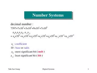
329 101 102 22 101 21 100 20 Unsigned Integers • Non-positional notation • could represent a number (“5”) with a string of ones (“11111”) • problems? • Weighted positional notation • like decimal numbers: “329” • “3” is worth 300, because of its position, while “9” is only worth 9 most significant least significant 3x100 + 2x10 + 9x1 = 329 1x4 + 0x2 + 1x1 = 5 Logic System Design I
Unsigned Integers (cont.) • An n-bit unsigned integer represents 2n values:from 0 to 2n-1. Decimal Logic System Design I
Unsigned Integer Practice • What is the decimal value of the unsigned binary number “1101”? • What is the binary representation of decimal 10? Logic System Design I
Unsigned Binary Arithmetic • Base-2 addition – just like base-10! • add from right to left, propagating carry carry 10010 10010 1111 + 1001 + 1011 + 1 11011 11101 10000 Logic System Design I
Unsigned Binary Arithmetic Practice • Base-2 addition – just like base-10! • add from right to left, propagating carry 10111 10111 + 1111- 1111 Subtraction, multiplication, division,… Logic System Design I
Signed Integers • With n bits, we have 2n distinct values. • assign about half to positive integers (1 through 2n-1)and about half to negative (- 2n-1 through -1) • that leaves two values: one for 0, and one extra • Positive integers • just like unsigned – zero in most significant bit00101 = 5 • Negative integers • sign-magnitude – set top bit to show negative, bottom as in unsigned10101 = -5 • one’s complement – flip every bit to represent negative11010 = -5 • in either case, most significant bit indicates sign: 0=positive, 1=negative Logic System Design I
Is there a better way? • Problems with sign-magnitude and 1’s complement • two representations of zero (+0 and –0) • arithmetic circuits are complex • How to add two sign-magnitude numbers? • e.g., try 2 + (-3) • How to add to one’s complement numbers? • e.g., try 4 + (-3) • There is a great representation of negative numbers that uses the analogy of an automobile odometer. Logic System Design I
Odometer numbers • Consider an odometer of a car at a location on a street: 0 0 1 3 Go 3 miles in reverse and it reads: 0 0 1 0 • Same as “subtracting 3” or “adding -3” • What happens when... 0 0 0 0 9 9 9 7 Go 3 miles in reverse and it reads: • As far as the odometer is concerned, 9997 = -3 • Note that fixed-width binary is very similar to odometer numbers in its limitations • Can the same representation be used? • 00002-00012=“11112” or -1 • 00002-00112=“11012” or -3 • This is called “2’s complement” Logic System Design I
Two’s Complement • Two’s complement representation developed to makecircuits easy for arithmetic. • for each positive number (X), assign value to its negative (-X),such that X + (-X) = 0 with “normal” addition, ignoring carry out 00101 (5) 01001 (9) + 11011(-5) + (-9) 00000 (0) 00000 (0) Logic System Design I
Two’s Complement Representation • If number is positive or zero, • normal binary representation, zeroes in upper bit(s) • If number is negative, • start with positive number • flip every bit (i.e., take the one’s complement) • then add one 00101 (5) 01001 (9) 11010 (1’s comp) (1’s comp) + 1+ 1 11011 (-5) (-9) Logic System Design I
Two’s Complement Signed Integers • MS bit is sign bit – it has weight –2n-1. • Range of an n-bit number: -2n-1 through 2n-1 – 1. • The most negative number (-2n-1) has no positive counterpart. Logic System Design I
Two’s Complement Practice • Show the two’s complement representation of the decimal number -6. Logic System Design I
Converting Binary (2’s C) to Decimal • If leading bit is one, take two’s complement to get a positive number. • Add powers of 2 that have “1” in thecorresponding bit positions. • If original number was negative,add a minus sign. X =01101000two = 26+25+23= 64+32+8 = 104ten Assuming 8-bit 2’s complement numbers. Logic System Design I
More Examples X =00100111two = 25+22+21+20 = 32+4+2+1 = 39ten X =11100110two -X = 00011010 = 24+23+21 = 16+8+2 = 26ten X = -26ten Assuming 8-bit 2’s complement numbers. Logic System Design I
Converting Binary (2’s C) to Decimal Practice • Convert binary 00011111 to decimal: Logic System Design I
Converting Decimal to Binary (2’s C) • First Method: Division • Divide by two – remainder is least significant bit. • Keep dividing by two until answer is zero,writing remainders from right to left. • Append a zero as the MS bit;if original number negative, take two’s complement. X =104ten104/2 = 52 r0 bit 0 52/2 = 26 r0 bit 1 26/2 = 13 r0 bit 2 13/2 = 6 r1 bit 3 6/2 = 3 r0 bit 4 3/2 = 1 r1 bit 5 X= 01101000two 1/2 = 0 r1 bit 6 Logic System Design I
Converting Decimal to Binary (2’s C) • Second Method: Subtract Powers of Two • Change to positive decimal number. • Subtract largest power of two less than or equal to number. • Put a one in the corresponding bit position. • Keep subtracting until result is zero. • Append a zero as MS bit; if original was negative, take two’s complement. X =104ten104 - 64 = 40 bit 6 40 - 32 = 8 bit 5 8 - 8 = 0 bit 3 X= 01101000two Logic System Design I
Converting Decimal to Binary Practice • Convert decimal 270 to binary using both methods described above: Logic System Design I
More Converting Decimal to Binary Practice • Convert decimal 255 to binary using both methods described above: Logic System Design I
Operations: Arithmetic and Logical • Recall: a data type includes representation and operations. • We now have a good representation for signed integers,so let’s look at some arithmetic operations: • Addition • Subtraction • Sign Extension • We’ll also look overflow conditions for addition. • Multiplication, division, etc., can be built from these basic operations. • Logical operations are also useful: • AND • OR • NOT Logic System Design I
Addition • As we’ve discussed, 2’s comp. addition is just binary addition. • assume all integers have the same number of bits • ignore carry out • for now, assume that sum fits in n-bit 2’s comp. representation 01101000 (104) 11110110 (-10) + 11110000(-16) +(-9) 01011000 (88) (-19) Assuming 8-bit 2’s complement numbers. Logic System Design I
Subtraction • Negate subtrahend (2nd no.) and add. • assume all integers have the same number of bits • ignore carry out • for now, assume that difference fits in n-bit 2’s comp. representation 01101000 (104) 11110110 (-10) - 00010000(16) -(-9) is just 01101000 (104) 11110110 (-10) + 11110000(-16) +(9) 01011000 (88)(-1) Assuming 8-bit 2’s complement numbers. Logic System Design I
Practice • Perform the Two’s Complement operation to the following decimal numbers: - 56 - 14 Logic System Design I
Sign Extension • To add two numbers, we must represent themwith the same number of bits. • If we just pad with zeroes on the left: • Instead, replicate the most significant bit -- the sign bit: 4-bit8-bit 0100 (4)00000100 (still 4) 1100 (-4)00001100 (12, not -4) 4-bit8-bit 0100 (4)00000100 (still 4) 1100 (-4)11111100 (still -4) Logic System Design I
Overflow • If operands are too big,then sum cannot be represented as an n-bit 2’s comp number. • We have overflow if: • signs of both operands are the same, and • sign of sum is different. • Another test -- easy for hardware: • carry into MS bit does not equal carry out 01000 (8) 11000 (-8) + 01001(9) + 10111(-9) 10001 (-15) 01111 (+15) Logic System Design I
Logical Operations • Operations on logical TRUE or FALSE • two states -- takes one bit to represent: TRUE=1, FALSE=0 • View n-bit number as a collection of n logical values • operation applied to each bit independently Logic System Design I
Examples of Logical Operations • AND • useful for clearing bits • AND with zero = 0 • AND with one = no change • OR • useful for setting bits • OR with zero = no change • OR with one = 1 • NOT • unary operation -- one argument • flips every bit 11000101 AND 00001111 00000101 11000101 OR 00001111 11001111 NOT11000101 00111010 Logic System Design I
Practice of Logical Operations • AND • useful for clearing bits • AND with zero = 0 • AND with one = no change • OR • useful for setting bits • OR with zero = no change • OR with one = 1 • NOT • unary operation -- one argument • flips every bit 10101010 AND 11100011 11001100 OR 00001111 NOT10010110 Logic System Design I
Hexadecimal Notation • It is often convenient to write binary (base-2) numbersas hexadecimal (base-16) numbers instead. • fewer digits -- four bits per hex digit • less error prone -- easy to corrupt long string of 1’s and 0’s Memorize this table!!!! Logic System Design I
Converting from Binary to Hexadecimal • Every four bits is a hex digit. • start grouping from right-hand side 011101010001111010011010111 3 A 8 F 4 D 7 This is not a new machine representation,just a convenient way to write the number. Logic System Design I
Converting from Hexadecimal to Decimal • Every hex digit position has a base value • multiply the value at the position by the base value 8 4 D 7 8x163 + 4x162 + 13x161 + 7x160= 8x4096 + 4x256 + 13x16 + 7x1 = 32768 + 1024 + 208 + 7 = 34007 Logic System Design I
Practice Converting from Hex to Decimal 6 F 6 A Logic System Design I
Octal • Octal is simply “base 8” number representation 010011010111 2 3 2 7 • Octal and Hex Practice 011010010101 Logic System Design I
Multiplication by example • Consider 210 x 310 multiplicand 0010 0011 multiplier copy of multiplicand 0010 0010 copy of multiplicand zero 0000 0000 zero 00000110 Logic System Design I
Division by example • Consider 3710÷ 310 11 ) 100101 Logic System Design I
Division by example - 2 • Consider 12410÷ 1110 1011 ) 1111100 Logic System Design I
BCD – Binary Coded Decimal (a.k.a. 8421 code) Four bits required, 0 thru 9 (or 00002 thru 10012) only represented, thus 235810 00100011010110002 Practice: encode 507,24510 as BCD • Gray Code – only one bit changes between successive code words. • 3-bit gray code will proceed as follows: • 000 001 011 010 110 111 101 100 • Application example: Aircraft altitude coding utilizes gray coding for altitude reporting to ATC (Air Traffic Control). Altitude is generally reported in 100 foot increments. Thus, every 100 feet only one bit changes. • Eg., 1000’ coded as (0320)8, 1100’ 03308 , 1200’ 03108, 1300’ 07108 Other coding schemas Logic System Design I
Error Detection and Correction (EDAC) • Errors can be detected and with proper coding techniques these detected errors can be corrected. • Parity bit is easiest to understand, • One bit added to data stream to make the number of ones either even or odd depending on the specification. • Eg., MS-bit is parity bit, system is odd parity, 8 data bits; transmission of 0x5C: • 101011100 – no error present, no error detected (5 ones, odd); • 101111100 – one error present, error detected (6 ones, even); • 100111100 – two errors present, no error detected (5 ones, odd); • Error detection always adds overhead, • Overhead … more bits to transmit serially, • Increased detection efficiency, equals increased overhead. • Error correction costs even more. • Understanding EDAC is particularly important in data communications. Logic System Design I
Text: ASCII Characters • ASCII: Maps 128 characters to 7-bit code. • both printable and non-printable (ESC, DEL, …) characters Logic System Design I
Data Communications • There was no standard for networks in the early days and as a result it was difficult for networks to communicate with each other. • The International Organization for Standardization (ISO) recognized this and in 1984 introduced the Open Systems Interconnection (OSI) reference model. • The OSI reference model organizes network functions into seven numbered layers. • Each layer provides a service to the layer above it in the protocol specification and communicates with the same layer’s software or hardware on other computers. • Layers 5-7 are concerned with services for the applications. • Layers 1-4 are concerned with the flow of data from end to end through the network Logic System Design I
Physical Layer (1) – Serial Communications • The basic premise of serial communications is that one or two wires are used to transmit digital data. • Of course, ground reference is also needed (extra wire) • Can be one way or two way, usually two way, hence two communications wires. • Often other wires are used for other aspects of the communications (ground, “clear-to-send”, “data terminal ready”, etc). 101101100111 Rx Tx Machine 2 Machine 1 Tx Rx 001101101111 Logic System Design I
Send one bit of the message at a time Message fields Start bit (one bit) Data (LSB first or MSB, and size – 7, 8, 9 bits) Optional parity bit is used to make total number of ones in data even or odd Stop bit (one or two bits) All devices on network or link must use same communications parameters The speed of communication must be the same as well (300, 600, 1200, 2400, 9600, 14400, 19200, etc.) More sophisticated network protocols have more information in each message Medium access control – when multiple nodes are on bus, they must arbitrate for permission to transmit Addressing information – for which node is this message intended? Larger data payload Stronger error detection or error correction information Request for immediate response (“in-frame”) Serial Communication Basics Data bits Message Logic System Design I
More on Serial communications … • Serial communications • Synchronous • Bit rate clock required, • Sync signal (identifies data word boundaries), • Data line. • Asynchronous • Bit rate known, • Eg., Computer comm port • UART (Universal Asynchronous Receiver/Transmitter) used to transmit and receive data. • Data modulation schemes • Some techniques: NRZ, DNRZ, NRZI, RZ, Miller and Manchester • Manchester is self clocking, • Bit rate knowledge is not required, • Design Tradeoff for reduced signal lines and synchronous behavior is doubled bandwidth. Logic System Design I
RS232: rules on connector, signals/pins, voltage levels, handshaking, etc. RS232: Fulfilling All Your Communication Needs, Robert Ashby Quick Reference for RS485, RS422, RS232 and RS423 Not so quick reference:The RS232 Standard: A Tutorial with Signal Names and Definitions, Christopher E. Strangio Bit vs Baud rates: http://www.totse.com/en/technology/telecommunications/bits.html Serial Communication Basics Logic System Design I