Number Systems
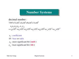
Number Systems. decimal number : 7397=7×10 3 +3×10 2 +9×10 1 +7×10 0 a 4 a 3 a 2 a 1 a 0 . a -1 a -2 = a 4 ×10 4 +a 3 ×10 3 +a 2 ×10 2 +a 1 ×10 1 +a 0 ×10 0 +a -1 x10 -1 +a -2 ×10 -2 a i : coefficient 10 : base or radix a 4 : most significant bit ( msb )

Number Systems
E N D
Presentation Transcript
Number Systems decimal number : 7397=7×10³+3×10²+9×101+7×100 a4a3a2a1a0 .a-1a-2 = a4×104 +a3×103+a2×102+a1×101+a0×100+a-1x10⁻¹+a-2×10⁻² ai : coefficient 10 : base or radix a4 : most significant bit ( msb ) a-2 : least significant bit ( lsb ) Digital Systems
In general, number N in a base-r system is represented as N = (anan-1......a1a0 .a-1a-2......a-m) which has the value N = (an.rn + an-1.rn-1 +......+a1.r+a0+a-1.r-1 + a-2 r-2 +......+a-m.r-m) In binary system﹐r = 2﹐ai {0, 1}. In octal system﹐r = 8﹐ai{0,1,…,7}. In decimal system﹐r = 10﹐ai {0,1,…,9}. In hexadecimalsystem﹐r = 16﹐ai{0,1,…9,A,B,C,D,E,F}. Digital Systems
Conversion between different Bases Base-r to base-10 conversion﹕ Straightforward﹗ Base-r to base-s conversion﹕ By repeated division for integers and repeated multiplication for fractions. Ex1. Convert (153.513)10 to octal number. Integer﹕ 153 (153)10 = (231)8 19 1 2 3 0 2 Digital Systems
fractional: 0.513×8 = 4.104 0.104×8 = 0.832 0.832×8 = 6.656 (0.513)10 = (0.4065…)8 0.656×8 = 5.248 (153.513)10 = (231.4065…)8 Ex2. Convert (12A)16 to octal. 1. Convert (12A)16 to (298)10 2. Convert (298)16 to octal as in Ex1. Digital Systems
Conversions between binary﹐octal﹐and hexadecimal can be done in a simpler way. Ex1. Convert (10111010011)2 to octal and hexadecimal. 10 111 010 011 (2723)8 2 7 2 3 101 1101 0011 (5D3)16 5 D 3 Ex2. Convert (12A7F)16 to binary and octal. 1 2 A 7 F 0001 0010 1010 0111 1111 binary 00 010 010 101 001 111 111 0 2 2 5 1 7 7 octal Digital Systems
Complement﹕for simplifying subtraction. Two types of complements for each base-r system﹕ (r-1)’s complement r’s complement The (r-1)’s complement of an n-digital number N﹕(rn 1) N Ex.In decimal system﹐the 9’s complement of 546700 is (106 1) 546700 = 999999 546700 = 453299 The 9’s complement of 012398 is 999999 012398 = 987601 The 1’s complement of 01011000 is (28 1) 01011000 = 11111111 01011000 = 10100111 The 1’s complement of 0101101 is 1010010. Digital Systems
The r’s complement of an n-digital number N﹕ rnNN ≠0 0 N = 0 Ex. The 10’s complement of 012398 is 987602. The 10’s complement of 2467000 is 7533000. The 2’s complement of 1101100 is 0010100. The 2’s complement of 0110111 is 1001001. Comments﹕ 1.To compute the complement of a number having radix point, first﹐remove the radix point﹐compute the complement of the new number﹐and restore the radix point. Ex. The 1’s complement of 01101.101 is 10010.010 The 2’s complement of 01101.101 is 10010.011 Digital Systems
2.The complement of the complement of N is N. (r1)’s complement of (2n 1) N = (2n 1) ((2n 1) N) = N Signed Binary Numbers Addition﹕ 9 1001 + 13 + 1101 22 10110 Subtraction﹕ 9 1001 13 1101 4 ? Digital Systems
How do we represent signed numbers in digital systems? representation of +9 with 8 bits: 00001001 representation of 9: signed magnitude: 10001001 signed -1’s-complement: 11110110 signed -2’s-complement: 11110111 Numbers that can be represented in n bits: signed magnitude: (2 n1+1) ~ (2 n 1 1) signed-1’s-complement: ( 2 n 1 +1) ~ (2 n 1 1) signed-2’s-complement: ( 2 n1) ~ (2 n1 1) Digital Systems
Summary: to perform arithmetic operations on signed magnitude numbers, we need to compare the signs and the magnitudes of the two numbers, and then perform either addition or subtraction. Addition and Subtraction on signed-magnitude numbers + 9 00001001 + 13 + 00001101 + 22 00010110 9 10001001 00001101 + 13 + 00001101 10001001 + 4 00000100 + 9 00001001 10001101 13 10001101 00001001 4 10000100 9 10001001 13 10001101 22 10010110 Digital Systems
Addition and subtraction on signed-2’s-complement numbers: Addition:add the corresponding digits ( including the sign digits) and ignore any carry out. + 9 00001001 9 11110111 + 13 + 00001101 + 13 + 00001101 + 22 00010110 + 4 100000100 discarded carryout Digital Systems
+ 9 00001001 13 + 11110011 4 11111100 the 2’s complement of 00000100 (4) 9 11110111 13 11110011 22 111101010 the 2’s complement of 00010110 (22) Discussion: ( N) + (M) (2n N) + M = 2n (N M) Case N > M: there will be no carry out, and the result is the 2’s complement of (N M) N M: = 2n + (MN) there will be a carry out, and the result after discarding the carry out is (M N) Digital Systems
overflow: + 64 01000000 64 11000000 + 96 + 01100000 96 +10100000 + 160 10100000 160 101100000 negative! positive! using 8 bits, we can represent only -128 ~ +127! When add two n-bits (including the sign bit) numbers N and M, overflow occurs when: 1. N, M 0, N+M 2n1 1 2. N, M < 0, N+M 2n1 Note that overflow cannot occur if one of N and M is positive and the other is negative. Digital Systems
Subtraction: N M = N+ ( M) = N + (2’s complement of M) 9 00001001 00001001 13 00001101 + 11110011 4 11111100 2’s complement of 00000100 Digital Systems
Addition and Subtraction on Signed-1’s-complement numbers: Assume that M, N 0, and they have n bits (including sign) Case M + N :normal binary addition. + 9 00001001 + 13 + 00001101 + 22 00010110 Case N + M : (1’s complement of N) + M = [(2n1) N] + M = (2n 1) (N M) Sub-case: N M 0: there will be no carry. Sub-case: N M 0: (2n 1) (N M) = 2n + (M N) 1 carry bit 0 So there will be a carry. To obtain (MN), we discard the carry and add 1 to the result. Digital Systems
Ex. 9 11110110 + 13 + 00001101 end-around carry + 4 100000011 + 1 00000100 Case ( N) + ( M) = (N+M) : (1’s complement of N) + (1’s complement of M) = [(2n1) N] + [(2n 1) M] = 2n 1 + (2n 1) (N+M) carry 1’s complement of (N+M) We obtain (2n 1)(NM) by discarding the carry and adding 1 to the result. 9 11110110 13 + 11110010 22 111101000 + 1 11101001 1’s complement of 00010110 (22) Digital Systems
Overflow: Similar to the case of 2’s complement, an overflow occurs when N+M 2n1 1or (N) + ( M) 2n1 +1 An overflow can be detected by examining the most significant bit of the result. + 64 01000000 (positive) + 96 + 01100000(positive) 160 10100000(negative) 64 10111111(negative) 96 10011111(negative) 160 101011110(positive) carry Digital Systems
Comparison of the three signed numbers systems : • signed-magnitude: • useful in ordinary arithmetic, awkward in computer arithmetic • signed-1’s-complement: • used in old computers, but is now seldom used. • signed-2’s-complement: • used in most computers. Digital Systems
Binary Codes Binary codes can be established for any set of discrete elements. Using n bits, we can represent at most 2ndistinct elements. So, to represent m distinct objects, we need at least log2m bits. For example, we need log210 = 4 bits to represent { 0,1,…9}. MAN(1) WOMAN (0) WHITE(00) RED(01) BLUE(10) BLACK(11) Digital Systems
Some possible binary codes are illustrated below. Decimal BCD Excess-3 84-2-1 2421 Bi-quinary digits (8421) (5043210) 0 0000 0011 0000 0000 0100001 1 0001 0100 0111 0001 0100010 2 0010 0101 0110 0010 0100100 3 0011 0110 0101 0011 0101000 4 0100 0111 0100 0100 0110000 5 0101 1000 1011 1011 1000001 6 0110 1001 1010 1100 1000010 7 0111 1010 1001 1101 1000100 8 1000 1011 1000 1110 1001000 9 1001 1100 1111 1111 1010000 Digital Systems
Alphanumeric Codes • -- ASCII (American Standard Code for Information Interchange) • originally use 7 bits to code 128 characters • since most digital systems handle 8-bit (byte) more efficiently, an 8 bit • version ASCII has also been developed. • -- EBDIC (Extended Binary-Coded Decimal Interchange Code) • used in most IBM systems • use 8 bits to code the same 128 character symbols as ASCII • Gray Code • each binary code differs from either its successor or predecessor by only • one bit. Digital Systems
Decimal Gray Code 0 0000 1 0001 2 0011 3 0010 4 0110 5 0111 6 0101 7 0100 8 1100 9 1101 10 1111 11 1110 12 1010 13 1011 14 1001 15 1000 4-bit Gray Code Digital Systems
A/D Converter Transmitter Receiver Gray Code is often used in situations where other binary code might produce erroneous or ambiguous results during transitions from one code to another. If we use BCD code to transmit 0111 (7) and then 1000 (8), then, an erroneous intermediate code 1001 may be generated if the rightmost bit takes more time to change. The Gray code eliminates this problem since only one bit changes between two consecutive numbers. Digital Systems
Generation of Gray Codes: an n-bits code is generated by reflecting the (n-1)-bit code. 0 0 00 000 0000 1 1 01 001 0001 1 11 011 0011 0 10 010 0010 10 110 0110 11 111 0111 01 101 0101 00 100 0100 100 1100 101 1101 111 1111 110 1110 010 1010 011 1011 001 1001 000 1000 Digital Systems
source destination Parity generator Parity detector ERROR Receiver Error-Detecting Code Binary code that can detect errors during data transmission. The most common ways to achieve error-detection is by means of aparity bit. A parity bit is an extra bit included in a binary code to make the total numberof 1’s transmitted either odd(odd parity) or (even parity). odd parityeven parity message parity bit message parity bit 0010 0 0010 1 0110 1 0110 0 1110 0 1110 1 1010 1 1010 0 Transmitter Digital Systems
x y Full Adder c z S x3 y3 x2 y2 x1 y1 x0 y0 FA FA FA FA c4 c0 c3 c2 c1 S3 S2 S1 S0 Digital Circuits Full Adder 4-bits Adder Digital Systems
Name Gate Algebraic Function Truth Table F = xy AND F = x+y OR F = x’ Inverter F = x Buffer NAND F = (xy)’ Digital Systems
F = (x+y)’ NOR Exclusive-OR (XOR) F = xy’+x’y = xy Exclusive-NOR (equivalence) F = xy+x’y’ = xy Digital Systems
xyz x y z Extension to multiple inputs Digital Systems
In real implementation, the three-input Exclusive-OR is usually implementedby 2-input Exclusive-OR: xy z xy z Even a two input Exclusive-OR is usually constructed with other types of gates. xy = x’y+xy’ x’y+y’x Digital Systems
This is how a gate adds a binary 1 and 0 in the “ones” place. If you feed a 1 and a 0 to the gate, it puts out a 1, which is the correct result of adding a binary 1 and 0. Place 1 1 +0 1 Digital Systems
Place Place 2 1 1 1 + 1 1 0 Addition with a carryover is a little more difficult, for instance, adding 1 plus 1. If you feed the gate a 1 and 1, it will put a 0 in the “ones” place and put a carryover of 1 in the “twos” place. This produces the correct result for adding 1 and 1 in binary. Digital Systems
c = f(x,y,z) = (3,5,6,7) s = (1,2,4,7) c: s: yy z x c = xy+yz+xz s = x’y’z+x’yz’+xy’z’+xyz y y z x Digital Systems
Various Implementations of a half-adder (b) S = (x+y)(x’+y’) C = xy (a) S = xy’+x’y C = xy Digital Systems
(c) S = (C + x’y’)’ C = xy (d) S = (x+y)(x’+y’) C = xy (e) S = xy C = xy Digital Systems
Binary Adder and Subtractor = x y z = xy + yz + xz 4-bit parallel adder Digital Systems
4-bit adder-subtractor Digital Systems