Download
1 / 30
330 likes | 392 Views
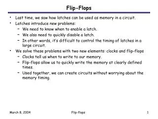
Explore Sequential Circuits, Latches, Flip-Flops, and Schematic Terminology. Learn about Sequential vs. Combinational Logic and Storage Elements in Chapter 4.

E N D
Sequential Circuits • Combinational Logic: • Output depends only on current input • Able to perform useful operations (add/subtract/multiply/encode/decode/ select[mux]/etc…) • Require cascading of many structures • Costly and inflexible Chapter 4: Sequential Circuits (4.1 -- 4.3)
Sequential Circuits (cont.) • Sequential Logic: • Output depends not only on current input but also on past input values • Store information between operations • Need some type of memory (Register) to remember the past input values. (Commonly use D type Flip Flops as Registers) Chapter 4: Sequential Circuits (4.1 -- 4.3)
Define Schematic Terminology P 4 I/Ps O/Ps 4 (P,Dout(3:0)) D(3:0) 5 Dout(3:0) Not a short circuit! Signals merge into a Bus or Vector D(3) D(3:0) D(2) D(1) D(0) Chapter 4: Sequential Circuits (4.1 -- 4.3)
Sequential Circuits (cont.) Information Storing Circuits – Registers(Flip Flops) Probably more than 1 bit if >2 states Timed “States” Chapter 4: Sequential Circuits (4.1 -- 4.3)
Sequential Logic: Concept • Sequential Logic circuits remember past inputs and past circuit state. • Outputs from the system are“fed back” as new inputs. • The storage elements are circuits that are capable of storing binary information: memory. Chapter 4: Sequential Circuits (4.1 -- 4.3)
Synchronous vs. Asynchronous machines There are two types of sequential circuits: • Synchronous sequential circuit: the behavior can be defined from knowledge of its signal at discrete instants of time. This type of circuits achieves synchronization by using a timing signal called the clock. • Asynchronous (fundamental mode) sequential circuit: the behavior is dependent on the order of input signal changes over continuous time, and output can change at any time (clockless). Chapter 4: Sequential Circuits (4.1 -- 4.3)
Clock Signal Rising Clock Edge Clock generator: Periodic train of clock pulses Different duty cycles Falling Clock Edge Chapter 4: Sequential Circuits (4.1 -- 4.3)
Synchronous Sequential Circuits:Flip flops as state memory • The flip-flops receive their inputs from the combinational circuit and also from a clock signal with edges (rising or falling) that occur at fixed intervals of time, as shown in the timing diagram. Chapter 4: Sequential Circuits (4.1 -- 4.3)
Storing Elements Can’t change the stored value! Inverters Buffers Chapter 4: Sequential Circuits (4.1 -- 4.3)
SR latch (NOR version) -- SR: “set-reset”, bistable element with two extra inputs; note the “undefined” output for S=R=1. -- Reading the logic: • Q = (R+Q’)’; P = (S+Q)’ Illegal state Chapter 4: Sequential Circuits (4.1 -- 4.3)
R=S=1 ?? • Illegal output, because • When S=R=1, both outputs go to zero. • If both inputs now go to 0, the state of the SR flip flop is depends on which input remains a 1 longer before making transition to 0. • Hence, “undefined” state. MUST be avoided. Chapter 4: Sequential Circuits (4.1 -- 4.3)
S’R’ Latch (NAND version) S’ R’ Q Q’ 0 S’ 1 Q 0 0 0 1 1 0 1 1 1 0 Set 0 Q’ 1 R’ X Y NAND 0 0 1 0 1 1 1 0 1 1 1 0 Chapter 4: Sequential Circuits (4.1 -- 4.3)
S’R’ Latch (NAND version) S’ R’ Q Q’ 1 S’ 1 Q 0 0 0 1 1 0 1 1 1 0 Set 0 Q’ 1 1 0 Hold R’ X Y NAND 0 0 1 0 1 1 1 0 1 1 1 0 Chapter 4: Sequential Circuits (4.1 -- 4.3)
S’R’ Latch (NAND version) S’ R’ Q Q’ 1 S’ 0 Q 0 0 0 1 1 0 1 1 1 0 Set 0 1 Reset 1 Q’ 0 1 0 Hold R’ X Y NAND 0 0 1 0 1 1 1 0 1 1 1 0 Chapter 4: Sequential Circuits (4.1 -- 4.3)
S’R’ Latch (NAND version) S’ R’ Q Q’ 1 S’ 0 Q 0 0 0 1 1 0 1 1 1 0 Set 0 1 Reset 1 Q’ 1 1 0 Hold R’ 0 1 Hold X Y NAND 0 0 1 0 1 1 1 0 1 1 1 0 Chapter 4: Sequential Circuits (4.1 -- 4.3)
S’R’ Latch (NAND version) S’ R’ Q Q’ 0 S’ 1 Q 1 1 Disallowed 0 0 0 1 1 0 1 1 1 0 Set 0 1 Reset 1 Q’ 0 1 0 Hold R’ 0 1 Hold X Y NAND 0 0 1 0 1 1 1 0 1 1 1 0 Chapter 4: Sequential Circuits (4.1 -- 4.3)
SR Latches Chapter 4: Sequential Circuits (4.1 -- 4.3)
SR Latch Simulation (Timing Diagram) Chapter 4: Sequential Circuits (4.1 -- 4.3)
SR Latch with Clock signal CLK CLK Latch is sensitive to input changes ONLY when C=1 Chapter 4: Sequential Circuits (4.1 -- 4.3)
S CLK R S R CLK S’ R’ Q Q’ SR Latch with Clock signal (cont.) S’ Q Q’ R’ 0 0 1 1 1 Q0 Q0’ Store 0 1 1 1 0 0 1 Reset 1 0 1 0 1 1 0 Set 1 1 1 0 0 1 1 Disallowed X X 0 1 1 Q0 Q0’ Store Chapter 4: Sequential Circuits (4.1 -- 4.3)
D Latch • One way to eliminate the undesirable indeterminate state in the RS flip flop is to ensure that inputs S and R are never 1 simultaneously. This is done in the D latch: CLK Chapter 4: Sequential Circuits (4.1 -- 4.3)
D D CLK Q Q’ 0 1 0 1 1 1 1 0 X 0 Q0 Q0’ D Latch (cont.) S S’ Q CLK Q’ R R’ S R CLK Q Q’ 0 0 1 Q0 Q0’ Store 0 1 1 0 1 Reset 1 0 1 1 0 Set 1 1 1 1 1 Disallowed X X 0 Q0 Q0’ Store Chapter 4: Sequential Circuits (4.1 -- 4.3)
Latches: Behaviour & Issues • Level triggered • Latches are “transparent” (= any change on the inputs is seen at the outputs immediately). • This causes synchronization problems! (not recommended for use in synchronous designs) • Solution: use latches to create flip-flops that can respond (update) ONLY on SPECIFIC times (instead of ANY time). Chapter 4: Sequential Circuits (4.1 -- 4.3)
Alternatives in FF choice • Edge triggered (rising or falling edge of clk) used in synchronous design • Various types exist: • RS • D • JK Chapter 4: Sequential Circuits (4.1 -- 4.3)
SR Flip Flop CLK CLK CLK Master Slave CLK • Enables edge-triggered behavior • This is NOT a latch (even though it is built from latches Chapter 4: Sequential Circuits (4.1 -- 4.3)
SR Flip Flop (contd.) S R CLK Q Q’ • When C=1, master is enabled and stores new data, slave stores old data. • When C=0, master’s state passes to enabled slave (Q=Y), master not sensitive to new data (disabled). 0 0 Q0 Q0’ Store 0 1 0 1 Reset 1 0 1 0 Set 1 1 1 1 Disallowed X X 0 Q0 Q0’ Store CLK CLK CLK Chapter 4: Sequential Circuits (4.1 -- 4.3)
Master-Slave J-K Flip-Flop CLK CLK CLK CLK Chapter 4: Sequential Circuits (4.1 -- 4.3)
Positive Edge-triggered D Flip-Flops • Attach level-triggered D latch to level-triggered SR latch, using complemented clocks. • D-Type Positive Edge-Triggered Flip-Flop: CLK CLK CLK Chapter 4: Sequential Circuits (4.1 -- 4.3)
Positive Edge-Triggered J-K Flip-Flop CLK CLK CLK Chapter 4: Sequential Circuits (4.1 -- 4.3)