Download
1 / 53
570 likes | 709 Views
Learn about fluid dynamics and statics, laminar and turbulent flow, Reynolds number, and practical applications in dosage form manufacturing and drug administration.

E N D
FLOW OF FLUIDS By Moizul Hasan Assistant Professor
FLUID FLOW A fluid is a substance that continually deforms (flows) under an applied shear stress. Fluids are a subset of the phases of matter and include liquids, gases. Fluid flow may be defined as the flow of substances that do not permanently resist distortion The subject of fluid flow can be divided into fluid static's and fluid dynamics
FLUID STATICS • Fluid static's deals with the fluids at rest in equilibrium • Behavior of liquid at rest • Nature of pressure it exerts and the variation of pressure at different layers Pressure differences between layers of liquids h1 Point 1 h2 Point 2
Consider a column of liquid with two openings Which are provided at the wall of the vessel at different height The rate of flow through these opening s are different due to the pressure exerted at the different height Consider a stationary columnthe pressure ps is acting on the surface of the fluid, column is maintained at constant pressure by applying pressure The force acting below and above the point 1 are evaluated Substituting the force with pressure x area of cross section in the above equation Force acting on the liquid At point 1 + Force excreted by the liquid Above point 1 = Force on the surface Pressure on the surface x area +mass x acceleration Pressure at point 1 xArea =
P1s = P2s + volume x density x acceleration = P2s + height x area x density x acceleration P1s = P2s +h1 S ρ g Since surface area is same P1 = Ps+ h1ρ g Pressure acting on point 2 may be written as P2 = Ps+ h2ρ g Difference in the pressure is obtained by P2 - P1 = g (Ps+ h2ρ )–( Ps+ h1ρ) g ∆P = (Ps+ h2ρ–Ps- h1ρ ) g = ∆ h ρg
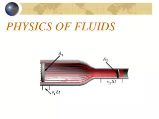
FLUID DYNAMICS • Fluid dynamics deals with the study of fluids in motion • This knowledge is important for liquids, gels, ointments which will change their flow behavior when exposed to different stress conditions MIXING FLOW THROUGH PIPES FILLED IN CONTAINER
TYPES OF FLOW Identification of type of flow is important in • Manufacture of dosage forms • Handling of drugs for administration The flow of fluid through a closed channel can be viscous or turbulent and it can be observed by Reynolds experiment Glass tube is connected to reservoir of water, rate of flow of water is adjusted by a valve, a reservoir of colored solution is connected to one end of the glass tube with help of nozzle. colored solution is introduced into the nozzle as fine stream
water valve Colored liquid LAMINAR OR VISCOUS FLOW TURBULENT FLOW
Laminar flow is one in which the fluid particles move in layers or laminar with one layer sliding with other • There is no exchange of fluid particles from one layer to other • When velocity of the water is increased the thread of the colored water disappears and mass of the water gets uniformly colored, indicates complete mixing of the solution and the flow of the fluid is called as turbulent flow • The velocity at which the fluid changes from laminar flow to turbulent flow that velocity is called as critical velocity
REYNOLDS NUMBER In Reynolds experiment the flow conditions are affected by • Diameter of pipe • Average velocity • Density of liquid • Viscosity of the fluid This four factors are combined in one way as Reynolds number Reynolds number is obtained by the following equation • Inertial forces are due to mass and the velocity of the fluid particles trying to diffuse the fluid particles • viscous force if the frictional force due to the viscosity of the fluid which make the motion of the fluid in parallel. D u ρ η INERTIAL FORCES = ------------------------------ = VISCOUS FORCES MASS X ACCELERATION OF LIQUID FLOWING ---------------------------------------------------------- SHEAR STRESS X AREA
At low velocities the inertial forces are less when compared to the frictional forces • Resulting flow will be viscous in nature • Other hand when inertial forces are predominant the fluid layers break up due to the increase in velocity hence turbulent flow takes place. • If Re < 2000 the flow is said to be laminar • If Re > 4000 the flow is said to be turbulent • If Re lies between 2000 to 4000 the flow change between laminar to turbulent
APPLICATIONS • Reynolds number is used to predict the nature of the flow • Stocks law equation is modified to include Reynolds number to study the rate of sedimentation in suspension Variations in the velocity of flow across the cross section When velocity is plotted against the distance from the wall following conclusions can be drawn • The flow of fluid in the middle of the pipe is faster then the fluid near to the wall • The velocity of fluid approaches zero as the pipe – wall is approached • At the actual surface of the pipe – wall the velocity of the fluid is zero
Pipe wall Turbulent flow Relative distance from the center of the pipe Viscous flow U / U max • The velocity of the fluid is zero at the wall surface there should be some layer in viscous flow near the pipe wall which acts as stagnant layer • if the flow is turbulent at the center and viscous at the surface a buffer layer exist, this buffer layer changes between the viscous to turbulent flow
BERNOULLI'S THEOREM When the principals of the law of energy is applied to the flow of the fluids the resulting equation is called Bernoulli's theorem • Consider a pump working under isothermal conditions between points A and B • Bernoulli's theorem states that in a steady state the total energy per unit mass consists of pressure, kinetic and potential energies are constant Kinetic energy = u2 / 2g Pump Pressure energy = Pa / ρAg Friction energy = F
At point a one kilogram of liquid is assumed to be entering at this point, pressure energy at joule can be written as Pressure energy = Pa /g ρA Where Pa = Pressure at point a g = Acceleration due to gravity ρA =Density of the liquid Potential energy of a body is defined as the energy possessed by the body by the virtue of its position Potential energy = XA Kinetic energy of a body is defined as the energy possessed by the body by virtue of its motion, kinetic energy = UA2 / 2g Total energy at point A = Pressure energy + Potential energy+ Kinetic energy
Total energy at point A = Pa /g ρA +XA +UA2 / 2g According to the Bernoulli's theorem the total energy at point A is constant Total energy at point A = Pa /g ρA +XA + UA2 / 2g = Constant After the system reaches the steady state, whenever one kilogram of liquid enters at point A, another one kilogram of liquid leaves at point B Total energy at point B = PB/g ρB +XB +UB2 / 2g INPUT = OUT PUT Pa /g ρA +XA +UA2 / 2g =PB /g ρB +XB +UB2 / 2g Theoretically all kinds of the energies involved in fluid flow should be accounted, pump has added certain amount of energy Energy added by the pump = + wJ
During the transport some energy is converted to heat due to frictional Forces Loss of energy due to friction in the line = FJ Pa /g ρA +XA +UA2 / 2g – F + W = PB /g ρB +XB +UB2 / 2g This equation is called as Bernoulli's equation Application • Used in the measurement of rate of fluid flow • It applied in the working of the centrifugal pump, in this kinetic energy is converted in to pressure.
MANOMETERS Manometers are the devices used for measuring the pressure difference Different type of manometers are there they are • Simple manometer • Differential manometer • Inclined manometer
SIMPLE MANOMETER • This manometer is the most commonly used one • It consists of a glass U shaped tube filled with a liquid A- of density ρA kg /meter cube and above A the arms are filled with liquid B of densityρB • The liquid A and B are immiscible and the interference can be seen clearly • If two different pressures are applied on the two arms the meniscus of the one liquid will be higher than the other • Let pressure at point 1 will be P1 Pascal's and point 5 will be P2 Pascal's • The pressure at point 2 can be written as = P1+ (m + R ) ρB g (m + R ) = distance from 3 to 5
P2 P1 5 1 m LIQUID B 4 R 3 2 Liquid A
Since the points 2 and 3 are at same height the pressure at 3 can be written as Pressure at 3 =P1+ (m + R ) ρB g Pressure at 4 can be written as = P2 + gm ρB or = P1+ ρB( m + R ) g- ρa R g Both the equations should be equal P2 + gm ρB= P1+ ρB( m + R ) g- ρa R g P1 – P2 = gm ρB-ρB( m + R) g + ρ A R g ∆P = gm ρB-gm ρB- R ρBg + R ρA =R (ρA-ρB)g
DIFFERENTIAL MANOMETERS • These manometers are suitable for measurement of small pressure differences • It is also known as two – Fluid U- tube manometer • It contains two immiscible liquids A and B having nearly same densities • The U tube contains of enlarged chambers on both limbs, • Using the principle of simple manometer the pressure differences can be written as ∆P =P1 –P2 =R (ρc – ρA) g
P2 P1 7 1 Liquid C a 2 6 b Liquid B 5 R 3 4 Liquid A
INCLINED TUBE MANOMETERS Many applications require accurate measurement of low pressure such as drafts and very low differentials, primarily in air and gas installations. In these applications the manometer is arranged with the indicating tube inclined, as in Figure, therefore providing an expanded scale. This enables the measurement of small pressure changes with increased accuracy.P1 –P2 = g R (ρA - ρB) sin α
MEASUREMENT OF RATE OF FLOW OF FLUIDS When ever fluid are used in a process it is necessary to measure the rate at which the fluid is flowing through the pipe, Methods of measurement are • Direct weighing or measuring • Hydrodynamic methods • Orifice meter • Venturi meter • Pitot meter • Rotameter • Direct displacement meter
DIRECT WEIGHING OR MEASURING The liquid flowing through a pipe is collected for specific period at any point and weighed or measured, and the rate of flow can be determined. Gases can not be determined by this method ORIFICE METER Principle: • Orifice meter is a thin plate containing a narrow and sharp aperture. • When a fluid stream is allowed to pass through a narrow constriction the velocity of the fluid increase compared to up stream • This results in decrease in pressure drop and the difference in the pressure may be read from a manometer The velocity of the fluid at thin constriction may be written as U0 =C 0√2g ∆H
∆H =can be measured by manometer C0 = constant U0 = velocity of fluid at the point of orifice meter CONSTRUCTION • It is consider to be a thin plate containing a sharp aperture through which fluid flows • Normally it is placed between long straight pipes • For present discussion plate is introduced into pipe and manometer is connected at points A and B WORKING • Orifice meter is referred as the variable head meter, i.e it measure the variation in the pressure across a fixed construction placed in the path of flow
When fluid is allowed to pass through the orifice the velocity of the fluid at point B increase, as a result at point A pressure will be increased. • Difference in the pressure is measured by manometer • Bernoulli's equation is applied to point A and point B for experimental conditions √U02 – UA2 =C0 √2g. ∆H U0 = velocity of fluid at orifice UA = velocity of fluid at point A C0 = constant • If the diameter of the orifice is 1/5 or less of the pipe diameter then UA is neglected Applications • Velocity at either of the point A and B can be measured • Volume of liquid flowing per hour can be determined
Throat of Venturi VENTURI METER Inlet section manometer
U v = C v√ 2g . ∆H DISADVANTAGES • Expensive • Need technical export • Not flexible it is permanent Advantages • Power loss is less • Head loss is negligible
Construction • It is also known as insertion tube • The size of the sensing element is small compared to the flow channel • One tube is perpendicular to the flow direction and the other is parallel to the flow • Two tubes are connected to the manometer ∆Hp = u2 /2g Working • Tube are inserted in the flow shown is the figure U2 = Cv√2g. ∆H • coefficient of Pitot tube
Construction • It consists of vertically tampered and transparent tube in which a plummet is placed • During the flow the plummet rise due to variation in flow • The upper edge of the plummet is used as an index to note the reading Working • As the flow is upward through the tapered tube the plummet rises and falls depend on the flow rate • Greater the flow rate higher the rise DIRECT DISPLACEMENT METER Used for the measurement of domestic water supply PRINCIPLE In this a stream of water enters meter and strikes the moving meter, the rate of rotation of the moving membrane is proportional to the velocity of the fluid.
Valves Valves are used to control the rate of fluid in a pipe Valves should withstand • Pressure • Temperature • Distortion it should made up of brass, iron, bronze, and cast iron E.X • Plug clock valve • Globe valve • Gate valve • Diaphragm valve • Quick opening valve • Check valve
PLUG CLOCK VALVE Stem Conical plug Cylindrical bore
It consists of casting body in to which a conical plug is fixed • The plug has an opening through liquid will flow • Packing material is included around the stem to close it Uses • Used for handling of gases • Used for wide opening or complete closing Dis advantages • Not suitable for water due to the material of which made • Some times plug will come out easily • For slight rotation also grate change in the flow so difficult to operate
GLOBE VALVE Globular body disc
Globe valve consists of a globular body with a horizontal internal portion • Passage of fluid is through a circular opening which can be opened and closed by inserting the disc • Disc is called as seating disc • It can be rotated freely on the stem Uses This should be used in pipe with size not more than 50 millimeters Disadvantage Rust, discomfort in opening of valve due to sludge