Download
1 / 1
10 likes | 204 Views
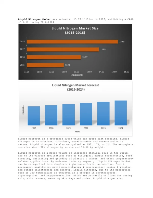
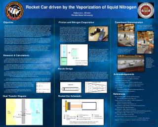
Rocket Car driven by the Vaporization of liquid Nitrogen. Rebecca L. Altman Florida State University. Objective. Friction and Nitrogen Evaporation. Experiment Demonstration. (Below) A cylindrical tube filled with water is placed inside the aluminum tube and then sealed.

E N D
Rocket Car driven by the Vaporization of liquid Nitrogen Rebecca L. Altman Florida State University Objective Friction and Nitrogen Evaporation Experiment Demonstration (Below) A cylindrical tube filled with water is placed inside the aluminum tube and then sealed. The goal of my summer project was to design and create a demonstration for the cryogenics laboratory that would be able to show the public the fundamentals of low temperature experimentation. I began this project by performing the past demonstrations and seeing how I could implement those ideas into my assignment. The three past demonstrations that I performed were: Balloons with gases, making superfluid Helium, and a Cork Rocket. The first experiment showed how different gases with different boiling points would react when placed in a liquid Nitrogen bath. The second experiment consisted of using liquid Nitrogen, a vacuum, and Helium gas to make Helium II (which is also called superfluid Helium). The third experiment consisted of a rocket with a cork at the end that was filled with liquid nitrogen and then tipped. As the pressure built up inside, there was enough force to cause the cork to shoot off into the air. Out of all the experiments, this one seemed like it had the most potential to be exciting, interesting, and educational. After doing a lot of research, I saw several demonstration videos by Julius Sumner Miller that sparked my interest. One of these included an experiment where he put dry ice (solid CO2), in a steel tube attached to a board with wheels. He then told the audience that given time, the dry ice would sublimate and cause the cork to pop off sending the car into motion. This idea sparked my interest in the possibility of a rocket car using liquid nitrogen instead of dry ice for the demonstration. I used Mathcad to conduct the calculations, the Explorer GLX to calculate the friction between the wheels of the car and the G-10 surface, and the resources in the cryogenics lab to complete the task. I was successfully able to design a “Rocket Car” that would run on the evaporation of liquid nitrogen. Room temperature water is mixed with liquid nitrogen at 77 K, creating an expedited evaporation of liquid nitrogen. The nitrogen gas combined with the water, creates the necessary impulse force to move the car. It was determined that this experiment would run best on a smooth surface so that less force would be needed to move the car. Since the cryogenics lab has spare G-10 pieces, I decided that this material would be used as the surface it would be run on. After running an experiment on the friction of the G-10 verses the wheels of the car, it was concluded that friction would be very low due to the smoothness of the surface material. The friction was determined by using the Force sensor on the Explorer GLX to give a graph of velocity. Then using the principles of dynamics, a free-body-diagram was made to gather the equations necessary to solve for friction. (It has also been determined that surfaces with low friction may also be used such as smooth plastic.) (Above) The Rocket Car is ready to begin so liquid nitrogen is poured into it via the top. After some test runs, I believe that some of the information given by the friction test could have been incorrect. To ameliorate the car, a tube of water was added to increase the amount of heat transferred to the liquid nitrogen. When the warm water mixes with the liquid nitrogen, it creates a rapid rate of vaporization of the liquid. This accelerated discharge of the nitrogen gas through the nozzle creates enough Impulse to cause the car to move forward. Research & Calculations (Left) The Rocket Car is launched by the liquid nitrogen inducing an Impulse that causes the car to accelerate. • Before beginning my project I did some research on cryogenics and thermal fluids so that I would have a general understanding of each. This research included learning about thermal conductivity and expansion, different types of heat transfer such as Fourier’s Law of Heat Conduction and Newton’s law of cooling, fluid flow, nozzle behaviors, and how the properties of different materials can effect the above. • Using software provided by Dr. Van Sciver, the amount of heat in the aluminum and liquid nitrogen was calculated. It was determined that 53.84 kJ of heat would need to be transferred to the nitrogen in order to evaporate it all (Q = 53.84 kJ). After this was determined, the following steps were taken in order to calculate the Impulse that would be produced, in addition to the diameter of the nozzle within the pressure requirement. • The time allowed for the experiment will be ten seconds. The rate of heat transfer given the allotted time is equal to 5.688 kW. This information is used in Newton’s law of cooling equation to calculate the heat transfer coefficient. The mass flow rate is then calculated, making is possible to use the pressure restriction of one atm to compute the velocity of fluid coming out of the orifice. (Eq. 1) • CD = the drag coefficient which is given a constant value of 0.65 • Using the basic definition of Impulse, (I = the change in momentum) the impulse is equal to 46.972 N*s. The force is calculated by using the relationship between force, time, and impulse (F = 4.697 N). (Eq. 2) • Applying the weight of the load on the car body, the friction due to the G-10 surface is calculated from the graphs produced by the Explorer GLX. Friction is calculated to be very small (0.423 N). Now it is known that the force created by the impulse will be enough to over come the forces of friction. • To find the diameter of the nozzle use (Eq. 3), resulting in d = 0.216 inches using (Eq. 4). (After going to the lab and seeing what was realistic, d = 0.208 in). Nozzle Design After much debate, I chose to have the nozzle be straight so that the actual construction of the nozzle would be easier, while still being able to make the demonstration occur. In theory, the converging nozzle would be the best fit due to the subsonic fluid which would be in motion. The enthalpy of the system would be converted into kinetic energy, which would cause the velocity to increase. A throat diameter would be a diameter smaller than the original diameter, which in turn would increase the pressure causing maximum velocity to be reached. In order to meet pressure restrictions, a converging/diverging nozzle would be needed to gradually reduce the pressure back to one atmosphere. Acknowledgements • Dr. Sylvie Fuzier and Dr. Steven W. Van Sciver (mentors) • Scott Maier (Assistance in the Cryogenics Laboratory) • The Cryogenics Department Staff • NHMFL REU Program, (CIRL) Center for Integrated Learning • Director: Pat Dixon Assistant Director: Jose Sanchez • National Science Foundation for funding the REU Program • Dr. Carl A. Moore • Florida State University, Mechanical Engineering Department • (Provided the Friction Testing Equipment) References Heat Transfer Diagram Rocket Car Schematic • Barron, Randall F. (1985). Cryogenic Systems (2nd ed.). • New York, NY: Oxford University Press, Inc. • Cengel, Yunus A., & Turner, Robert H. (2005). Fundamentals of • Thermal-Fluid Sciences (2nd ed.). • New York, NY: McGraw-Hill Companies, Inc. • Janna, William S. (1998). Design of Fluid Thermal Systems (2nd ed.). • Boston, MA: PWS Publishing Company • Scott, Russell B. (1988). Cryogenic Engineering. • Boulder, CO: National Bureau of Standards Cryogenic Engineering Laboratory • Scurlock, Ralph G. (Eds.). (1992). History and Origins of Cryogenics • New York, NY: Oxford University Press • Miller, Julius Sumner. Gases and Liquids Part Two • http://www.youtube.com/watch?v=vdujCy6nTSQ Western Video Industries • Wikipedia, The Free Encyclopedia. 17 July 2007, Wikimedia Foundation, Inc. • http://en.wikipedia.org