Download
1 / 23
230 likes | 408 Views
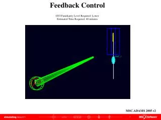
Feedback Control GUI Familiarity Level Required: Lower Estimated Time Required: 40 minutes. MSC.ADAMS 2005 r2. Topics Covered. In this tutorial you will learn how to:. Create cylinder Create frustum Rename part Modify orientation Modify mass properties

E N D
Feedback Control GUI Familiarity Level Required: Lower Estimated Time Required: 40 minutes MSC.ADAMS 2005 r2
Topics Covered In this tutorial you will learn how to: • Create cylinder • Create frustum • Rename part • Modify orientation • Modify mass properties • Create distance along axis (DX) function • Create velocity along axis (VX) function • Add translational joint • Create simple harmonic function • Add translational joint motion • Add torque If you have any difficulties, import the “Pulley_System_shortcut_1.cmd” file and proceed from pg 13 If you have any difficulties, import the “Pulley_System_shortcut_2.cmd” file and proceed from pg 16 If you have any difficulties, import the “Pulley_System_shortcut_3.cmd” file and proceed from pg 19 If you have any difficulties, import the “Pulley_System_complete.cmd” file and proceed from pg 24
Feedback Control Problem This example shows how you can simply model a closed-loop feedback control system using standard modeling functionality, such as measures. The model does not require any controls specific entities such as state variables or transfer functions. The model introduces how ADAMS can be useful in understanding the effects that a control system will have on your physical system.
What You Should Accomplish When you complete this tutorial you will have a model that illustrates an object following the motion of a second motion
This particular model simulates a pointer that is attempting to follow the movement of a translating block. This task could easily be accomplished imposing a motion on the pointer that matches the motion of the block. However, many physical systems use a control system to act as an imposed motion. Control systems are not perfect and do induce error when compared to the ideal motion of the system. The control system in this model uses two measures as input and outputs one torque value. The control system emulates a proportional-derivative (PD) type controller. Thus, we can use a distance measure to calculate the proportional portion and a velocity measure to find the derivative portion of the controller.
Getting Started • Start ADAMS • Create new model (Model Name = Feedback_Control, Gravity = No Gravity, Units MKS) • Turn on Length checkbox, enter (0.1m) in text field • Turn on Radius checkbox, enter (0.1m) in text field • Click (0,0,0) (1,0,0) a e d b c
Rename • Right-click on cylinder, select Part: PART_2 Rename • Enter .Feedback_Control.Pointer in New name text field • Click OK b c a
Modify Orientation • Right click cylinder, select Marker: MARKER_1 Modify • Enter (0.0,0.0,0.0) in Orientation text field • Click OK a b c
Create Frustum • Select Frustum from Rigid Body tool stack • Select Add to Part from Frustum pull down menu • Turn on Length checkbox, enter (1.0m) in text field • Turn on Bottom Radius checkbox, enter (5.0E-002m) in text field • Turn on Top Radius checkbox, enter (1.0E-002m) in text field • Click Pointer (1.0. 0.0. 0.0) (1.0. 0.0. 0.0) Pointer.MARKER_1 a b f c d e
Modify Mass Properties • Right click on Pointer, select Part: Pointer Modify • Select User Input from Define Mass by pull down menu • Enter 1.0 in Mass text field • Enter 1.0 in Ixx, Iyy, Izz text field • Enter cm in Center of Mass Marker text field • Click OK a b c d e f
Create Slider • Create a cylinder (Length = (0.4m), Radius = (0.1m)), from (1.25, -0.2, 0.0) to (1.25, 0.2, 0.0) • Rename .Feedback_Control.Slider • Modify Slider properties: Mass =1.0, Ixx = Iyy = Izz = 1.0 • Enter Slider.cm in Center of Mass Marker text field • Enter Slider.cm in Inertia Reference Marker text field • Rename Slider cm to .Feedback_Control.Slider.slider_center • Rename MARKER_2 at tip of Frustum to .Feedback_Control.Pointer.tip
Create Measures • Click Build menu Measure Function New • Enter .Feedback_Conrol_Displacement_Error in Measure Name text field • Select Diplacement from pull down menu • Click Distance along X • Click Assist • Enter slider_center in To Marker text field • Enter tip in From Marker text field • Enter tip in Along Marker text field • Verify that the Create a Function Measure text field reads: DX(slider_center, tip, tip) • Click OK a i f c b e d g h j
Create Measure Create another measure with name .Feedback_Control.Velocity_Error. The function should read: VX(slider_center, tip, tip)
Add Translational Joint • Select Translational joint from joint tool stack • Select 1 Location from Construction pull down menu • Click Slider.slider_center Positive Y direction (slider_center.Z) • Select Translational joint motion from Motion Driver tool stack • Click JOINT_1
Modify Translational Joint Motion • Right-click JOINT_1, select Motion: MOTION_1 Modify • Click button next to Function (time text) field • Enter: • SHF(TIME,0,.5,6.28,0,0) • +SHF(time, 0.0, 0.1, 6.28*4, 0.0, 0.0) • In Define a runtime function • Click OK a c b d
Add Torque • Select Torque from Force tool stack • Click Pointer Pointer.MARKER_1 • Rename .Feedback_Control.Plant a a
Modify Torque Function • Right-click torque, select Torque: SFORCE_1 Modify • Click button next to Function text field a b
Modify Torque Function Enter 10*Displacement_Error+ 10*Velocity_Error in Define a runtime function text field
Model This is what your screen should look like when your model is complete
Verify Your Model Verify your model, should have 6 degrees of freedom and no redundant constraints Run simulation (Duration = 5, Step Size = 0.01)
Topics Covered In this tutorial you will learn how to: • Create cylinder • Create frustum • Rename part • Modify orientation • Modify mass properties • Create distance along axis (DX) function • Create velocity along axis (VX) function • Add translational joint • Create simple harmonic function • Add translational joint motion • Add torque
Best Practices • Make sure that the units are MKS • Make sure that gravity is turned off • Check location of parts • Check orientation of joints • Verify that the functions are calling values • Verify model