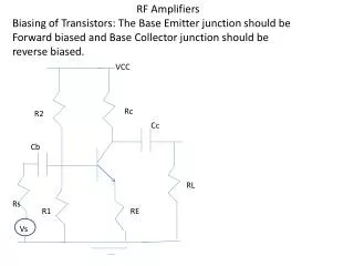
RF POWER AMPLIFIERS
RF POWER AMPLIFIERS. 1.1 ideal parallel-Tuned Circuit. Ideal parallel-tuned circuit 은 parallel LC 회로이다 . Tuning freq f0 에서 zero conductance (infinite impedance) 이다 . 그 외 frequency 에서 infinite conductance ( zero impedance ) 이다 .

RF POWER AMPLIFIERS
E N D
Presentation Transcript
1.1 ideal parallel-Tuned Circuit • Ideal parallel-tuned circuit 은 parallel LC 회로이다. • Tuning freq f0 에서 zero conductance (infinite impedance) 이다. • 그 외 frequency 에서 infinite conductance ( zero impedance )이다. • Load resister R에연결시sinusoidal current 가 load 통해 흐른다.
1.2 ideal Series-Tuned Curcuit • Ideal series-tuned circuit 은 series LC 회로 • Tuning freq f0 에서 zero impedance 이다. • 그 외 frequency 에서 infinite impedance 이다. • Load resister R에연결 시 sinusoidal current 가 load 통해 흐른다.
1.3 Efficiency • RF power amp 의 중요한 parameter 이다. • 즉 output power versus input power . • Input power 는 dc input power 와 RF input power 로 구성
Collector Efficiency • 로 정의 한다. • P0 는 RF output power , Pdc = VdcIdc • Po 는보통 RF fundamental power 와 RF harmonics power 포함 • Harmonics power 를 무시하기 때문에 P0 는 RF fundamental power 로 근사함
1.4 power output capability • Power output capability 는 device 가 1V 의 peak collector voltage 와 1A 의 peak collector current 일 때 output power 로써 정의.
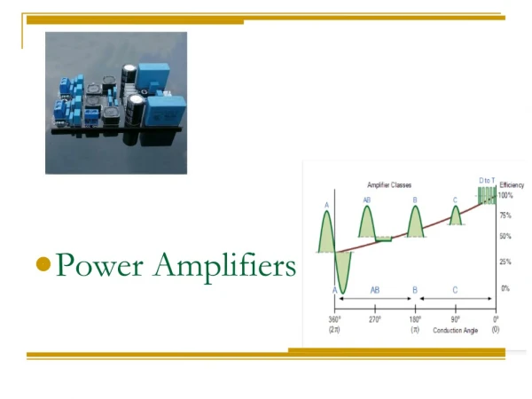
2장 Classic RF power Amplifiers Class A, AB, B, C 등이 있다. Active device 가 controlled-current source 로 작동 Active 영역에서의 RF cycle 부분을 conduction angle =2 라고 함.
Class conduction angle • Class A => 2 =360 degree • Class AB = > 180 <2 < 360 • Class B => 2 =180 degree • Class C => 2 < 180 degree
2.1 Class A amplifiers • Active 영역에서 RF angle 동안 360 degree conduction angle 보장
Single-end Class A 분석 • RF choke 는 ideal . [ RF choke 란 ? 즉 RF 를 완전히 죽인다. -> 증폭기 와 같은 능동 회로는 반드시 capacitor 붙임으로 외부 유출 막을 수 있다. 한편 RF 교류 신호도 DC 바이어스단으로 흘러 들어가지 않도록 막아야 하는데 그러한 역할 하는 모든 회로구조를 RFC 라 함 ] RF choke 는 input current 허용 • 는 dc block capacitor • Active device 는 ideal controlled-current source 로 처리 • Saturation voltage or/and Saturation current 무시
Class A collector efficiency • Transistor 가 active 영역에서 , 일 때 효율이 50% 정도 나온다. 적은 효율은 Class A 의 단점중 하나이다.
some observation and practical consideration 1.class A 는저항 load 와 넓은 주파수 범위 사용 하지만 active device 가 비선형일때 왜곡 피할 수 없다. 그래서 load 에 filter 설치 2.Push –pull circuit 은두 개의 동일한 TR 에의해 output power 결합 -> 대부분의 harmonics 를 cancel 가능 ,단 회로구성이 복잡함 3.Class A는선형 전송 특성과 높은 power gain 표현 가능 ,하지만 낮은 efficiency load 때문에 class A amplifier 는대체로 low level driver 로 사용 4.Load current 의 harmonics distortion 은 collector 전류의 고조파 와 공진회로의 Q factor 있으면 쉽게 계산 가능
Class B and AB ampilifier Push-pull circuit -> push-pull circuit 의두 개의 (Q1,Q2) 장치는 180 degree 의 위상차로 번갈아 가며 작동 (alternately active) RF cycle 의반은 cut off
Class b 회로 동작 기존적인 분석은 Class A와 같음 Output Tr T2 는 ideal Primary winding 에서 m이 turn in 되고 secondary winding 에서 n 이 turn in 된다. 반 주기에서 peak vale I의 a half sinusoidal current 는 T2 의 Primary winding 의반주기 동안 운반 (Fig 2-5 참고)
Class B 의 collector efficiency • 처음 반주기가 저항 통과 시 두 번째 는 open • Class A (50%) 에 비해 증가 • Drive signal 없으면 Transistor 둘 다 cut off 즉 power 소모 없다. • 75.8 % 에서 실제는 60 ~ 70 % 정도이다. • Capability 는 1/8 = 0.125 로 Class A와 같다.
some observation and practical consideration 1.Class B 는 tuned circuit 이나 band or low pass filter 가 필수적으로 요구 되지는 않는다. 2.push-pull class B 는 linear 를 위한 선택이다. Output harmonic current 나 inter modulation 은 Class A에 비해서는 썩 좋지는 않다. 단지 Efficiency 가 매우 높아짐 3.Small Quiescent current 가 crossover distortion 을 제거 하는데 이용 4.만약 push-pull efficiency 이 완전히 symmetry 라면 output current 는 고조파 생성하지 않는다.
2.3 Class C amplifier • 장점: Class C 는 Class A, AB ,B 보다 collector Efficiency 가 높다. • 단점: output harmonics 가 다른 Class 보다 더 높고 , 추가적으로 filtering 과 낮은 power gain 요구 • Most popular analysis techniques 는 transistor 이 active 일 때 sine wave 의 한 부분이 collector current waveform 과 근사함
Current-source Class Amplifiers 상태: transistor 이 RF cycle 동안 saturation 되지 않음 Active device 는 cutoff and active region -> active region 에서 Controlled-current source Class A, AB, B 와 다르게 Class C 는 parallel-tuned circuit 요구 RF cycle -> active 영역에서 Collector current 는 sine wave 의 한 부분만을 사용 ->180 degree 보다 적은 부분
RF cycle • 360 degree 로 확장해서 보면 cycle 의 amplitude 는 I • 적은 입력 범위로 신호 입력
Current-source Class Amplifiers • Ideal 한 tuned circuit 때문에 output current 는 sinusoidal 즉 Maximum theoretical collector efficiency 는 conduction angle 에 따라 달라 진다.
결과 분석 • Collector efficiency 는 class A, AB ,B 보다 Class C 가 더 높다. Conduction angle 감소 할수록 증가. • Power output capability 는 0.125 보다 감소 ,Conduction angle 감소 할수록 감소 • Output power 얻는 것이 중요 결과적으로 conduction angle 선택은 collector efficiency 와 collector current peak value 사이의 Trade off d. Class C 에서 conduction angle 은 DC bias voltage Vb에 의해 control 된다. -> conduction angle 이감소함에 따라서 power gain 감소
Saturated Class C Amplifiers • Saturated 된 operate 2가지 장점 첫째. Output power, collector efficiency, power output capability 의 증가가 가능 둘째. Output signal 의 amplitude 가 주로 DC-supply voltage 의존
Saturated Class C Amplifiers • Active 영역에서 transistor 는 controlled-current source 로 작동
Class c Mixed mode Amplifiers • 1. 분석과 디자인 위한 많은 parameter는 데이터 시트가 제공되지 않고, 측정과 계산이 매우 어렵다. • 2. 실제 회로 control 하기 극히 어렵다. • 3. sinusoidal collector voltage 얻기가 거의 불가능하다 • 4. bjt를 drive bias 하기 어렵다.