Download
1 / 57
600 likes | 802 Views
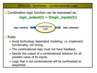
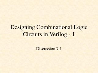
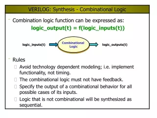
Designing Combinational Logic Circuits in Verilog - 1. Discussion 7.1. Designing Combinational Logic Circuits in Verilog - 1. Gates Multiplexers Adder Subtractor. Hardware Description Languages. Verilog ABEL VHDL. We will only cover Verilog VHDL is taught in CSE 378. Verilog.

E N D
Designing Combinational Logic Circuits in Verilog - 1 Discussion 7.1
Designing Combinational Logic Circuits in Verilog - 1 • Gates • Multiplexers • Adder • Subtractor
Hardware Description Languages • Verilog • ABEL • VHDL We will only cover Verilog VHDL is taught in CSE 378
Verilog source code gates.v module gates(x,y,invx,invy,andd,orr,nandd,norr,xorr,xnorr); input x; input y; output invx; output invy; output andd; output orr; output nandd; output norr; output xorr; output xnorr; assign invx = ~x; assign invy = ~y; assign andd = x & y; assign orr = x | y; assign nandd = ~(x & y); assign norr = ~(x | y); assign xorr = x ^ y; assign xnorr = x ~^ y; endmodule
Pin numbers set it separate file:gates.ucf NET "x" LOC = "p11"; NET "y" LOC = "p7"; NET "invx" LOC = "p35"; NET "invy" LOC = "p36"; NET "andd" LOC = "p37"; NET "nandd" LOC = "p39"; NET "orr" LOC = "p40"; NET "norr" LOC = "p41"; NET "xorr" LOC = "p43"; NET "xnorr" LOC = "p44";
Gates.v module gates ( X ,Z, Y ); input [4:1] X ; wire [4:1] X ; output [6:1] Z ; wire [6:1] Z ; output [6:1] Y ; wire [6:1] Y ; and(Z[6],X[1],X[2],X[3],X[4]); nand(Z[5],X[1],X[2],X[3],X[4]); or(Z[4],X[1],X[2],X[3],X[4]); nor(Z[3],X[1],X[2],X[3],X[4]); xor(Z[2],X[1],X[2],X[3],X[4]); xnor(Z[1],X[1],X[2],X[3],X[4]); assign Y[6] = &X; assign Y[5] = ~&X; assign Y[4] = |X; assign Y[3] = ~|X; assign Y[2] = ^X; assign Y[1] = ~^X; endmodule Verilog gate level primitives Verilog reduction operators
and(Z[6],X[1],... nand(Z[5],X[1], ... or(Z[4],X[1], ... nor(Z[3],X[1], ... xor(Z[2],X[1], ... xnor(Z[1],X[1], ... assign Y[6] = &X; assign Y[5] = ~&X; assign Y[4] = |X; assign Y[3] = ~|X; assign Y[2] = ^X; assign Y[1] = ~^X;
Implementing Combinational Logic Circuits in Verilog • Gates • Multiplexers • Adder • Subtractor
4 x 1 MUX s1 s0 Y 0 0 C0 0 1 C1 1 0 C2 1 1 C3 Multiplexers C0 C1 Y C2 C3 s1 s0
4 x 1 MUX Multiplexers s1 s0 Y C0 0 0 C0 0 1 C1 1 0 C2 1 1 C3 C1 Y C2 C3 s1 s0 A multiplexer is a digital switch 0 0
4 x 1 MUX Multiplexers s1 s0 Y C0 0 0 C0 0 1 C1 1 0 C2 1 1 C3 C1 Y C2 C3 s1 s0 0 1
4 x 1 MUX Multiplexers s1 s0 Y C0 0 0 C0 0 1 C1 1 0 C2 1 1 C3 C1 Y C2 C3 s1 s0 1 0
4 x 1 MUX Multiplexers s1 s0 Y C0 0 0 C0 0 1 C1 1 0 C2 1 1 C3 C1 Y C2 C3 s1 s0 1 1
A 2 x 1 MUX Z = A & ~s0 | B & s0
A 4 x 1 MUX A = ~s0 & C0 | s0 & C1 B = ~s0 & C2 | s0 & C3 Z = ~s1 & A | s1 & B Z = ~s1 & (~s0 & C0 | s0 & C1) | s1 & (~s0 & C2 | s0 & C3)
A 4 x 1 MUX Z = ~s1 & (~s0 & C0 | s0 & C1) | s1 & (~s0 & C2 | s0 & C3) Z = ~s1 & ~s0 & C0 | ~s1 & s0 & C1 | s1 & ~s0 & C2 | s1 & s0 & C3
A 4 x 1 MUX case(s) 2'b00 : Z = C0; 2'b01 : Z = C1; 2'b10 : Z = C2; 2'b11 : Z = C3; default: Z = C0; endcase
s Y 0 A 1 B ProblemHow would you make aQuad 2-to-1 MUX? Quad 2-to-1 MUX [A3..A0] [Y3..Y0] [B3..B0] s
mux.v module mux24(A,B,s,Y); input [3:0] A; input [3:0] B; input s; output [3:0] Y; wire [3:0] Y; assign Y = {4{~s}} & A | {4{s}} & B; endmodule Quad 2-to-1 MUX [A3..A0] [Y3..Y0] [B3..B0] s
module mux24(A,B,s,Y); input [3:0] A; input [3:0] B; input s; output [3:0] Y; wire [3:0] Y; assign Y = {4{~s}} & A | {4{s}} & B; endmodule
mux.v module mux24a(A,B,s,Y); input [3:0] A; input [3:0] B; input s; output [3:0] Y; reg [3:0] Y; always @(A,B,s) if(s == 0) Y = A; else Y = B; endmodule Quad 2-to-1 MUX [A3..A0] [Y3..Y0] [B3..B0] s
module mux24a(A,B,s,Y); input [3:0] A; input [3:0] B; input s; output [3:0] Y; reg [3:0] Y; always @(A,B,s) if(s == 0) Y = A; else Y = B; endmodule
mux.v module mux24(A,B,s,Y); input [3:0] A; input [3:0] B; input s; output [3:0] Y; wire [3:0] Y; assign Y = s ? B : A; endmodule Quad 2-to-1 MUX [A3..A0] [Y3..Y0] [B3..B0] s
Implementing Combinational Logic Circuits in Verilog • Gates • Multiplexers • Adder • Subtractor
A 0 S 0 B 0 C 1 Half Adder A B S C 0 0 0 1 0 0 0 0 0 1 1 0 1 0 1 0 1 1 0 1 Dec Binary 1 1 +1 +1 2 10
Multiple-bit Addition A3 A2 A1 A0 B3 B2 B1 B0 0 1 0 1 0 1 1 1 A B Ci+1 +Ci 0 1 0 1 0 1 1 1 1 1 1 Ai +Bi A B Si 1 1 0 0
AiBi 00 01 11 10 Ci 0 1 Si Full Adder Ci Ai Bi Si Ci+1 0 0 0 0 0 0 0 1 1 0 0 1 0 1 0 0 1 1 0 1 1 0 0 1 0 1 0 1 0 1 1 1 0 0 1 1 1 1 1 1 1 1 1 1
Full Adder Ci Ai Bi Si Ci+1 Si = ~Ci & ~Ai & Bi | ~Ci & Ai & ~Bi | Ci & ~Ai & ~Bi | Ci & Ai & Bi 0 0 0 0 0 0 0 1 1 0 0 1 0 1 0 0 1 1 0 1 1 0 0 1 0 1 0 1 0 1 1 1 0 0 1 1 1 1 1 1
Full Adder Si = ~Ci & ~Ai & Bi | ~Ci & Ai & ~Bi | Ci & ~Ai & ~Bi | Ci & Ai & Bi Si = ~Ci & (~Ai & Bi | Ai & ~Bi) | Ci & (~Ai & ~Bi | Ai & Bi) Si = ~Ci & (Ai ^ Bi) | Ci & (Ai~^ Bi) Si = Ci ^ (Ai ^ Bi)
AiBi 00 01 11 10 Ci 0 1 Ci+1 Full Adder Ci Ai Bi Si Ci+1 0 0 0 0 0 0 0 1 1 0 0 1 0 1 0 0 1 1 0 1 1 0 0 1 0 1 0 1 0 1 1 1 0 0 1 1 1 1 1 1 1 1 1 1
AiBi 00 01 11 10 Ci 0 1 Full Adder Ci Ai Bi Si Ci+1 0 0 0 0 0 0 0 1 1 0 0 1 0 1 0 0 1 1 0 1 1 0 0 1 0 1 0 1 0 1 1 1 0 0 1 1 1 1 1 1 1 1 1 1 Ci+1 Ci+1 = Ai & Bi | Ci & Bi | Ci & Ai
AiBi 00 01 11 10 Ci 0 1 Full Adder Ci Ai Bi Si Ci+1 0 0 0 0 0 0 0 1 1 0 0 1 0 1 0 0 1 1 0 1 1 0 0 1 0 1 0 1 0 1 1 1 0 0 1 1 1 1 1 1 1 1 1 1 Ci+1 Ci+1 = Ai & Bi | Ci & ~Ai & Bi | Ci & Ai & ~Bi
Full Adder Ci+1 = Ai & Bi | Ci & ~Ai & Bi | Ci & Ai & ~Bi Ci+1 = Ai & Bi | Ci & (~Ai & Bi | Ai & ~Bi) Ci+1 = Ai & Bi | Ci & (Ai ^ Bi) Recall: Si = Ci ^ (Ai ^ Bi) Ci+1 = Ai & Bi | Ci & (Ai ^ Bi)
Half-adder Half-adder Full Adder Si = Ci ^ (Ai ^ Bi) Ci+1 = Ai & Bi | Ci & (Ai ^ Bi)
Full Adder A full adder can be made from two half adders (plus an OR gate).
Full Adder Block Diagram
4-Bit Adder C 1 1 1 0 A 0 1 0 1 B0 1 1 1 S 1 1 0 0
adder4.v module adder4(A,B,S,Cout); input [3:0] A; input [3:0] B; output [3:0] S; output Cout; wire [3:0] S; wire [4:0] C; assign C[0] = 0; // zero carry in assign S = A ^ B ^ C[3:0]; assign C[4:1] = A & B | (A ^ B) & C[3:0]; assign Cout = C[4]; endmodule
adder4.v module adder4(A,B,S); input [3:0] A; input [3:0] B; output [3:0] S; reg [3:0] S; always @(A, B) begin S = A + B; end endmodule
4-Bit Adder C 1 1 1 0 0:A 0 1 1 0 1 0:B 0 0 1 1 1 C4:S 1 0 1 0 0
adder.v module adder4(A,B,S,carry); input [3:0] A; input [3:0] B; output [3:0] S; output carry; reg [3:0] S; reg carry; reg [4:0] temp; always @(A, B) begin temp = {1'b0,A} + {1'b0,B}; S = temp[3:0]; carry = temp[4]; end endmodule Note: In the sensitivity list a comma can be used in place of or in Verilog 2001 Concatenate a leading 0
Implementing Combinational Logic Circuits in Verilog • Gates • Multiplexers • Adder • Subtractor
A 0 D 0 B 0 C 1 Half Subtractor A B D C 0 0 0 1 0 0 0 0 0 1 1 1 1 0 1 0 1 1 0 0 2 1 0 -1 1
Multiple-bit Subtraction A3 A2 A1 A0 B3 B2 B1 B0 0 1 0 1 0 1 1 1 A B Ci+1 - Ci 0 1 0 1 0 1 1 1 1 1 Ai - Bi A B Di 1 1 1 1 0
AiBi 00 01 11 10 Ci 0 1 Di = Ci ^ (Ai ^ Bi) Same as Si in full adder Full Subtractor Ci Ai Bi Di Ci+1 0 0 0 0 0 0 0 1 1 1 0 1 0 1 0 0 1 1 0 0 1 0 0 1 1 1 0 1 0 1 1 1 0 0 0 1 1 1 1 1 1 1 1 1 Di
AiBi 00 01 11 10 Ci 0 1 Full Subtractor Ci Ai Bi Di Ci+1 0 0 0 0 0 0 0 1 1 1 0 1 0 1 0 0 1 1 0 0 1 0 0 1 1 1 0 1 0 1 1 1 0 0 0 1 1 1 1 1 1 1 1 1 Ci+1 Ci+1 = ~Ai & Bi | Ci & ~Ai & ~Bi | Ci & Ai & Bi
Full Subtractor Ci+1 = ~Ai & Bi | Ci & ~Ai & ~Bi | Ci & Ai & Bi Ci+1 = ~Ai & Bi | Ci & (~Ai & ~Bi | Ai & Bi) Ci+1 = ~Ai & Bi | Ci & ~(Ai ^ Bi) Recall: Di = Ci ^ (Ai ^ Bi) Ci+1 = ~Ai & Bi | Ci & ~(Ai ^ Bi)
half subtractor half subtractor Full Subtractor Di = Ci ^ (Ai ^ Bi) Ci+1 = ~Ai & Bi | Ci & ~(Ai ^ Bi)