Office Automation System : Design Database
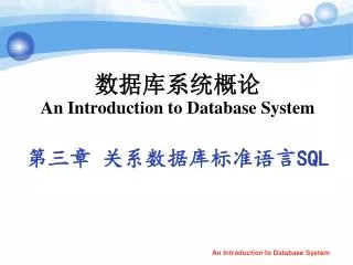
Chapter 5. Office Automation System : Design Database. SUCHADA PUNNOI Dept. of Computer Science & Information Technology http :// computer . pcru . ac . th / suchada/. Download & Contact ME. Download Documents http :// computer . pcru . ac . th / KuBo/ 4122602_OA.php FQA

Office Automation System : Design Database
E N D
Presentation Transcript
Chapter 5 Office Automation System : Design Database SUCHADA PUNNOI Dept. of Computer Science & Information Technology http://computer.pcru.ac.th/suchada/
Download & Contact ME • Download Documents • http://computer.pcru.ac.th/KuBo/4122602_OA.php • FQA • http://computer.pcru.ac.th/KuBo/com_title/show_forum.php • Contact ME • Office : LC BuildingRoomcom201 • Website : http://computer.pcru.ac.th/KuBo/ • Phone : 056 - 717100Ext.4503 • E-Mail : suchada@pcru.ac.th
วงจรชีวิตการพัฒนาฐานข้อมูล Database Life Cycle : DBLC วิเคราะห์ความต้องการ Initial Study ออกแบบฐานข้อมูล Database Design บำรุงรักษา Maintenance สร้างฐานข้อมูล Implement and Loading ใช้งานจริง Operation ทดสอบระบบฐานข้อมูล Testing and Evaluation
Database Life Cycle :DBLC • Database Initial Study :วิเคราะห์ความต้องการของผู้ใช้ • Data Design :ออกแบบฐานข้อมูล (Data Driven, Joint Data and Function-driven) • Implementation and Loading :สร้างเป็นฐานข้อมูล • Testing and Evaluation :ทดสอบฐานข้อมูลที่สร้าง • Operation :ใช้งานฐานข้อมูล • Maintenance and Evaluation :บำรุงรักษาฐานข้อมูล
การออกแบบฐานข้อมูลมีประโยชน์อย่างไรการออกแบบฐานข้อมูลมีประโยชน์อย่างไร • เป็นการวางแผนว่าจะเก็บข้อมูลต่างๆ ที่จำเป็นต้องใช้ในระบบงานไว้ในตารางใดบ้าง โดยยังคงมีความสัมพันธ์ระหว่างข้อมูลไว้ได้ และสามารถเรียกดูข้อมูลที่เก็บไว้เพื่อมาใช้งานได้ตามปกติ • มองเห็นความสัมพันธ์ระหว่างข้อมูลทั้งหมดที่มีอยู่ โดยข้อมูลบางตัวอาจจะเกี่ยวข้องกับข้อมูลอื่นๆหลายตัว อาจทำให้เกิดการเก็บรายละเอียดของข้อมูลนั้นซ้ำซ้อนกันได้
ขั้นตอนในการออกแบบฐานข้อมูลขั้นตอนในการออกแบบฐานข้อมูล 1. Requirement Analysis Database Designer (ER-Diagram) 2. Conceptual Design 3. Logical Design (Normalization) 4. Schema Refinement DBA 5. Physical Design 6. Security Design 7. Maintenance
1. สำรวจความต้องการใช้งาน(Requirement Analysis) • เป็นขั้นตอนแรกที่สำคัญมากต่อระบบฐานข้อมูล • จะรู้ความต้องการของผู้ใช้งานและระบบได้อย่างไร
จะรู้ความต้องการของผู้ใช้งานได้อย่างไรจะรู้ความต้องการของผู้ใช้งานได้อย่างไร • ศึกษาเอกสารที่ใช้ในระบบงานนั้นๆ • การใช้แบบสอบถาม • การพูดคุยกับผู้ใช้โดยตรง • ข้อมูลที่เราจำเป็นต้องเก็บรวบรวมเพื่อนำไปใช้ในการออกแบบระบบฐานข้อมูล ประกอบด้วย • ข้อมูลแต่ละตัวที่จำเป็นต้องใช้ในระบบงาน(Entity) • รายละเอียดของข้อมูลนั้น(Attribute) • ความสัมพันธ์ระหว่างข้อมูลทั้งหมด(Relationship)
ตั้งคำถาม ถามระบบ • วิธีที่จะตรวจสอบว่าความต้องการที่สำรวจได้เพียงพอที่จะใช้งานจริงแล้วหรือไม่ คือ ลองตั้งคำถามที่ต้องการดูว่าข้อมูลที่จะเก็บในฐานข้อมูลสามารถนำมาใช้ตอบคำถามนั้นๆได้ทั้งหมดหรือไม่ • ถ้าตอบได้ ก็แสดงว่าเราไม่ได้ลืมเก็บข้อมูลที่จำเป็นต้องใช้ตัวอื่นอีก
2. ออกแบบฐานข้อมูลระดับแนวคิด(Conceptual Design) • หลังจากได้ความต้องการแล้ว ก็จะทำการออกแบบเชิงแนวคิด(conceptual design) • โดยใช้ตัวแบบข้อมูลเชิงแนวคิด (conceptual data model) เช่น ER-Model ในการออกแบบเค้าร่างเชิงแนวคิด • ผู้ออกแบบฐานข้อมูลจะต้อง • กำหนดเอนติติ้และแอตทริบิวต์ • กำหนดคอนสเตรนต์ • กำหนดความสัมพันธ์ • หลังจากได้เค้าร่างเชิงแนวคิดแล้ว ผู้วิเคราะห์ระบบจะนำเค้าร่างเชิงแนวคิดไปยืนยันกับผู้ใช้ถึงความต้องการทั้งหมด เพื่อให้แน่ใจว่าไม่ได้หลงลืมความต้องการหรือข้อมูลบางส่วนไป
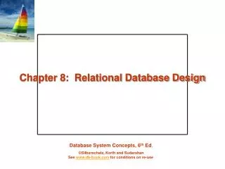
3. ออกแบบฐานข้อมูลระดับตรรกะ(Logical Design) • เมื่อได้ออกแบบเค้าร่างเชิงแนวคิดที่ได้รับการยืนยันจากผู้ใช้แล้ว ก็จะจัดทำการออกแบบเชิงตรรกะ (logical design) เพื่อออกแบบเค้าร่างเชิงตรรกะ(logical schema) ให้เป็นไปตามตัวแบบข้อมูลของระบบการจัดการฐานข้อมูล • เป็นขั้นตอนการแปลง ER-Diagram ไปเป็นตารางตาม Relational data Model
4. ปรับโครงสร้างข้อมูล(Schema Refinement) • ตารางที่ได้จากการออกแบบฐานข้อมูลในระดับ Logical ยังไม่ใช่ตารางที่เหมาะสำหรับนำไปเก็บข้อมูลจริง เนื่องจากอาจทำให้เกิดความซ้ำซ้อนของข้อมูล และปัญหาต่างๆ เช่น ปัญหาการเพิ่มข้อมูล(Insert Anomaly) • ขั้นตอนนี้ เป็นการปรับโครงสร้างตาราง โดยการทำ Normalization ซึ่งจะทำให้ได้จำนวนตารางมากขึ้นกว่าเดิมแต่ปัญหาต่างๆจะถูกกำจัดออกไป
5. ออกแบบฐานข้อมูลระดับกายภาพ(Physical Design) • เป็นหน้าที่ DBA เพื่อให้ระบบฐานข้อมูลเกิดประสิทธิภาพมากที่สุด • การออกแบบในระดับนี้ เกี่ยวข้องกับการสร้างอินเด็กซ์ (Index)และการเลือกโครงสร้างข้อมูลระดับภายใน (Internal View) เพื่อให้สอดคล้องกับลักษณะการใช้งานข้อมูลที่เกิดขึ้นบ่อยๆ เช่น สร้างอินเด็กซ์ที่คอลัมน์ซึ่งมักถูกใช้กำหนดเป็นเงื่อนไขในการดึงข้อมูล
6. ควบคุมการนำไปใช้(Security Design) • เป็นการกำหนดสิทธิในการใช้งานข้อมูลที่ DBA จะกำหนดขึ้นตามความเหมาะสมและความต้องการของผู้ใช้งาน
7. การบำรุงรักษาระบบ(Maintenance Database System) • เป็นขั้นตอนที่มีความสำคัญกับระบบมาก • เมื่อระบบทำงานช้าลง ต้องตรวจสอบ • เมื่อพบข้อผิดพลาดจากข้อมูลที่เก็บ • เมื่อความต้องการของระบบหรือผู้ใช้เปลี่ยนไป • เมื่อนโยบายขององค์กรเปลี่ยนไป • การสำรองข้อมูล เมื่อไร backup / การกู้คืนข้อมูล • การป้องกันไวรัสทุกชนิด โจรกรรมข้อมูล
การออกแบบฐานข้อมูล • เป็นเรื่องที่สำคัญมาก เพราะมีผลต่อประสิทธิภาพในการใช้งาน • ควรออกแบบอย่างรอบคอบ • โดยต้องทำความเข้าใจในระบบงานก่อน • เพื่อให้การออกแบบถูกต้องและครอบคลุมงานของระบบทั้งหมด ป้องกันการแก้ไขภายหลังหรือป้องกันความซ้ำซ้อนของงานที่ออกแบบ
Entity Relationship Data Model • โดย ดร.ปีเตอร์ เชนน์ ราวปี ค.ศ. 1976 • ER data model จัดเป็น conceptual data model ที่ใช้ออกแบบฐานข้อมูลได้อย่างอิสระ ไม่ต้องคำนึงถึงว่าจะใช้ DBMS ชนิดไหน ยี่ห้ออะไร ด้วยคุณสมบัติเด่นนี้ทำให้ ER-model เป็นที่นิยมใข้งานกันมากในการวิเคราะห์และออกแบบฐานข้อมูล • ผลการออกแบบด้วย ER-model สามารถแสดงด้วยรูปภาพ หรือ ER-Diagram • นักวิเคราะห์และออกแบบสามารถใช้ ER-Diagram เสมือนเป็นเครื่องมือในการอธิบายองค์ประกอบ(Basic Structure) และ ข้อกำหนดเงื่อนไข(Integrity constraint) ของฐานข้อมูล
Entity Relationship Data Model(ต่อ) • นำ ER-Diagram ไปใช้ทบทวนยืนยันความเข้าใจที่ถูกต้องกับ user ของระบบงานได้ เพราะ ER-Diagram ประกอบด้วยสัญลักษณ์ที่สื่อความหมายเข้าใจได้ง่าย • เมื่อได้ ER-Diagram ที่ถูกต้องเหมาะสมกับระบบงานแล้วและทราบแล้วว่าจะใช้ DBMS ชนิดใด จึงจะทำการแปลง (Mapping) ให้ได้เป็น Logical schema ที่ตรงกับ DBMS
เทคนิคการสร้างแผนภาพความสัมพันธ์ระหว่างข้อมูล Entity Relationship Model • กำหนด Entity • Strong Entity • Weak Entity • กำหนด Attribute • Composite attribute • Simple attribute • Single-value attribute • Multivalued attributes • Derived attributes • กำหนด Primary Key • กำหนด Relationship • 1:1 • 1:M • M:N • ชนิดความสัมพันธ์ • Unary/Recursive • Binary • Ternary • EER
Entity Weak Entity Relationship Symbol (Chen) Owner Relationship
Attribute Primary Key Composite Attribute Derived Attribute Symbol (Chen) Multivalue Attribute
E1 E2 R E1 E2 R 1 N Symbol (Chen) partial Total Cardinality Ratio
Symbol ชนิดของความสัมพันธ์
การแปลงแผนภาพความสัมพันธ์เป็นรีเลชั่น Translation of ER Model to Relational Model
Step 1 – Entities • Steps in transforming entities • Create one table for each entity • The name of the table is the name of the entity • The names of the columns are the names of attributes of entity • The primary key of the table is the primary key of the entity
S_ID Firstname BirthYear Lastname Transforming Entities: Example Students
Step 2: One-to-Many Relationships • Steps in transforming one-to-many relationships • Add the primary key of the one side as column of the many side • The column will be the foreign key referencing the primary key of the referenced table • Steps in transforming many-to-one relationships are the same
N 1 Student Instructor Has_advisor BirthYear Phone Transforming one-to-many relationship S_ID Firstname Lastname I_ID Firstname Lastname
Step 3: Many-to-Many Relationships • Steps in transforming many-to-many relationships • Many-to-many relationships become their own tables • Primary keys of participating entities together form the primary key of this table • These columns are at the same time foreign keys referring to the primary keys of the participating entities • Attributes of the relationship become attributes of this table
M N Student Course takes Transforming many-to-many relationship S_ID … C_ID …
Transforming many-to-many relationship (2) M N Student Course takes Registration_date S_ID … C_ID …
Renaming of Attributes • Columns of the same table must have different names • E.g. if ‘ID’ is the name of primary key attributes of two tables, one must be renamed before it can be added to another table • Renaming can be done in both the original attribute and the added attribute • One renaming guideline is by adding entity name with attribute, e.g. student_id, instructor_id, etc. • Or add relationship name with attribute, e.g. advisor_id, manager_id, etc.
N 1 Product Customer Bought_by … ID ID … Renaming of Attributes (2) • Example Attribute Rename
1 1 Department Employee managed_by D_ID … E_ID … Step 4: One-to-One Relationships • Normally, the translation is the same for one-to-many relationships • Add the primary key of one side as an attribute of the other side • Example:
1 1 Department Employee managed_by Transforming One-to-One Relationship D_ID … E_ID …
(1,1) (0,1) (0,1) (1,1) (1,1) (0,1) E1 E1 E1 E2 E2 E2 R R R Transforming One-to-One Relationship (2) • For a better design, transforming one-to-one relationship should be separated for 3 cases of one-to-one relationships:
Transforming One-to-One Relationship: (0,1) and (1,1) • It is better to add the primary key of the (0,1) side as an attribute of the (1,1) side to avoid null values • Example (1,1) (0,1) Department Employee managed_by D_ID … E_ID …
(0,1) (0,1) Employee Office has E_ID … O_ID … Transforming One-to-One Relationship: (0,1) and (0,1) • Put the primary key of any of the two tables into the other table (null values can’t be avoided) • Or transform the relationship into a table(avoid null)
(0,1) (0,1) Employee Office has E_ID … O_ID … Transforming One-to-One Relationship: (0,1) and (0,1)(2)
Transforming One-to-One Relationship: (1,1) and (1,1) • Merge the two tables into one table • Choose primary key of one table to be the primary key of this table • Primary key of the other table becomes alternate key of this table
Transforming One-to-One Relationship: (1,1) and (1,1)(2) (1,1) (1,1) Customer CreditCard has C_ID Name CNum CreditLimit
Translation of Advanced ER-Constructs • Weak Entities • Specialization • Structured, Multivalued Attributes
Weak Entities • Weak entity usually has many-to-one relationship (or one-to-one) with the master entity • However, transforming weak entities is simpler than transforming normal many-to-one or one-to-one relationship • Steps in transforming weak entities • Create a table for a weak entity • Inherits the primary key attributes of every master entity • Together with the partial key of the weak entity, they form the primary key of this table • These attributes become foreign keys referencing the tables of master entities
Transforming Weak Entities (1,*) Building Room has … … Building_name Room_number
Specialization • There is no direct support for specialization in Relational Model • Supported in Object-oriented and Object-relational models • There are 3 possible methods of converting specialization in ER Model to Relational Model • Method 1: One table with a lot of null value • Method 2: Different tables for subclasses • Method 3:Splitting of attributesover tables
Example ID Employee Name Pilot FlightHours
Transforming Specialization: Method 1 • One table with a lot of null value • Add all attributes of superclass and subclass into one table with additional attribute, e.g. Is_Pilot • Example of DB State
Transforming Specialization: Method 1 (2) • Advantages of Method 1 • No join is needed (which will improve query performance) • The number of table is minimized (single table) • Most frequently used in practice • Disadvantage • Relationship of subclass can not be represented easily, e.g. relationship between ‘pilot’ and ‘aircraft’ entity
Transforming Specialization: Method 2 • Different table for subclass • One table for subclass with all attributes inherited from superclass • Store information of ‘normal employee’ separated from ‘pilot’