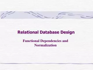
Relational Database Design by ER-to-Relational Mapping
480 likes | 1.41k Views
Relational Database Design by ER-to-Relational Mapping. Outline. Review Relational model ER model ER diagram Database design steps ER-to-Relational Mapping Algorithm Enhanced ER (EER and mapping). Relational Model Concepts.

Relational Database Design by ER-to-Relational Mapping
E N D
Presentation Transcript
Outline • Review • Relational model • ER model • ER diagram • Database design steps • ER-to-Relational Mapping Algorithm • Enhanced ER (EER and mapping)
Relational Model Concepts • The relational Model of Data is based on the concept of a Relation. • A Relation is a mathematical concept based on the ideas of sets. • The strength of the relational approach to data management comes from the formal foundation provided by the theory of relations.
Relation = table • RELATION: A table of values • A relation may be thought of as a set of rows. • A relation may alternately be though of as a set of columns. • Each row represents a fact that corresponds to a real-world entity or relationship. • Each row has a value of an item or set of items that uniquely identifies that row in the table. • Sometimes row-ids or sequential numbers are assigned to identify the rows in the table. • Each column typically is called by its column name or column header or attribute name.
Schema of a relation • The Schema of a Relation: R (A1, A2, .....An) Relation schema R is defined over attributes A1, A2, .....An An example - CUSTOMER (Cust-id, Cust-name, Address, Phone#) • Here, CUSTOMER is a relation defined over the four attributes Cust-id, Cust-name, Address, Phone#. • Each attribute has a domain or a set of valid values. For example, the domain of Cust-id is 6 digit numbers. Usually specified by a proper data types and certain check constraints.
Relational Database Schema • A Relational Database: Information are modeled by multiple relations interlinked explicitly by foreign keys. • A set S of relation schemas that belong to the same database. S is the name of the database. S = {R1, R2, ..., Rn}
A relational schema ofCOMPANY,Actually the Result of the mapping of the ER schema.
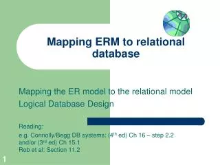
ER model • The ER model describes data in a mini-world as entities, relationships and attributes, as well as constraints associated with the relationships.
ER diagrams • ER model schema can be displayed by means of the graphical notation known as ER diagrams. • ER diagram notations
E1 SUMMARY OF ER-DIAGRAM NOTATION FOR ER SCHEMAS Symbol Meaning ENTITY TYPE WEAK ENTITY TYPE RELATIONSHIP TYPE IDENTIFYING RELATIONSHIP TYPE ATTRIBUTE KEY ATTRIBUTE MULTIVALUED ATTRIBUTE COMPOSITE ATTRIBUTE DERIVED ATTRIBUTE TOTAL PARTICIPATION OF E2 IN R CARDINALITY RATIO 1:N FOR E1:E2 IN R R E2 N R E1 E2
ER Model Concepts – Mini-world • Mini-world: Some part of the real world about which data is stored in a database. • For example, student grades and transcripts at a university. • Or all empolyees and departments in a company
ER Model Concepts -Attributes • Attributes are properties used to describe a specific object or a set of objects (as we have learned, formally called an entity or a set of entities). • For example an EMPLOYEE is an object, it may have a Name, SSN, Address, Sex, BirthDate • Each attribute has a value set (or data type) associated with it – e.g. integer, string, subrange, enumerated type, … • A specific object (entity) will have a value for each of its attributes. • For example a specific employee may have Name='John Smith', SSN='123456789', Address ='731, Fondren, Houston, TX', Sex='M', BirthDate='09-JAN-55‘ • Attributes can be used for relationship also!
ER Model Concepts – entities and entity sets • Entities are specific objects or things in the mini-world that are represented in the database. • For example the EMPLOYEE John Smith, the Research DEPARTMENT, the ProductX PROJECT • Entities with the same basic attributes are grouped or typed into an entity set (represented by a entity type). • For example, the EMPLOYEE entity type or the PROJECT entity type.
ENTITY SET corresponding to theENTITY TYPE CAR CAR Registration(RegistrationNumber, State), VehicleID, Make, Model, Year, (Color) car1 ((ABC 123, TEXAS), TK629, Ford Mustang, convertible, 1999, (red, black)) car2 ((ABC 123, NEW YORK), WP9872, Nissan 300ZX, 2-door, 2002, (blue)) car3 ((VSY 720, TEXAS), TD729, Buick LeSabre, 4-door, 2003, (white, blue)) . . .
Weak Entity Types • An entity that does not have a key attribute • A weak entity must participate in an identifying relationship type with an owner or identifying entity type • Entities are identified by the combination of: • A partial key of the weak entity type • The particular entity they are related to in the identifying entity type Example: Suppose that a DEPENDENT entity is identified by the dependent’s first name and birhtdate, and the specific EMPLOYEE that the dependent is related to. DEPENDENT is a weak entity type with EMPLOYEE as its identifying entity type via the identifying relationship type DEPENDENT_OF
Weak Entity Type is: DEPENDENTIdentifying Relationship is: DEPENDENTS_OF
ER Model Concepts – Relationships • A relationship relates two or more distinct entities with a specific meaning. • For example, EMPLOYEE John Smith works on the ProductX PROJECT • or EMPLOYEE Franklin Wong manages the Research DEPARTMENT.
ER Model Concepts - Relationship Types • Relationships of the same type are grouped or typed into a relationship type. • For example, the WORKS_ON relationship type in which EMPLOYEEs and PROJECTs participate, • or the MANAGES relationship type in which EMPLOYEEs and DEPARTMENTs participate. • The degree of a relationship type is the number of participating entity types. • Both MANAGES and WORKS_ON are binary relationships. • Other properties of relationship types
Constraints on Relationships • Constraints on Relationship Types • ( Also known as ratio constraints ) • Maximum Cardinality • One-to-one (1:1) • One-to-many (1:N) or Many-to-one (N:1) • Many-to-many • Minimum Cardinality (also called participation constraint or existence dependency constraints) • zero (optional participation, not existence-dependent) • one or more (mandatory, existence-dependent)
Many-to-one (N:1) RELATIONSHIP EMPLOYEE WORKS_FOR DEPARTMENT e1 e2 e3 e4 e5 e6 e7 r1 r2 r3 r4 r5 r6 r7 d1 d2 d3
Many-to-many (M:N) RELATIONSHIP r9 e1 e2 e3 e4 e5 e6 e7 r1 r2 r3 r4 r5 r6 r7 p1 p2 p3 r8
Example of a Database(with a Conceptual Data Model) • Mini-world for the example: Part of a UNIVERSITY environment. • Some mini-world entities: • STUDENTs • COURSEs • SECTIONs (of COURSEs) • (academic) DEPARTMENTs • INSTRUCTORs Note: The above could be expressed in the ENTITY-RELATIONSHIP data model.
Example of a Database(with a Conceptual Data Model) • Some mini-world relationships: • SECTIONs are of specific COURSEs • STUDENTs take SECTIONs • COURSEs have prerequisite COURSEs • INSTRUCTORs teach SECTIONs • COURSEs are offered by DEPARTMENTs • STUDENTs major in DEPARTMENTs Note: The above could be expressed in the ENTITY-RELATIONSHIP data model. Question: how to draw ER diagram for this example?
Two models • Relational model is a model used at logical design phase, favoring RDBMS. • ER model is a model used at conceptual design phase, favoring human being.
Two models • From implementation point view • It is DBMS specific • how to model data depends on what model the DBMS system is built upon. • Relational model • In our case, Oracle is a RDBMS, therefore in a Oracle database application, information are supposed to be tailored into relational model. • Favoring RDBMS • From conceptual design point view • It is DBMS-independent • ER model, ER diagram • Favoring human being • Facilitating the analysis of the user requirements at conceptual level
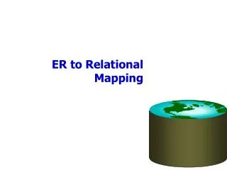
How to bridge two models? • ER-to-Relational Mapping Algorithm
Data Models • Data Model: A set of concepts to describe the structure of a database,and certain constraints that the database should obey. • The emphasis is on representing the attributes of the instances rather than the instances themselves. • Data Model Operations: Operations for specifying database retrievals and updates by referring to the concepts of the data model. Operations on the data model may include basic operations and user-defined operations.
Categories of data models • Conceptual (high-level, semantic) data models: Provide concepts that are close to the way many users perceive data. • Physical (low-level, internal) data models: Provide concepts that describe details of how data is stored in the computer. Binary Files on disks, index structures etc. • logical (representational) data models: Provide concepts that fall between the above two, balancing user views with some computer storage details. Implementation interface of physical model.
Outline • ER-to-Relational Mapping Algorithm Step 1: Mapping of Regular Entity Types Step 2: Mapping of Weak Entity Types Step 3: Mapping of Binary 1:1 Relation Types Step 4: Mapping of Binary 1:N Relationship Types. Step 5: Mapping of Binary M:N Relationship Types. Step 6: Mapping of Multivalued attributes. Step 7: Mapping of N-ary Relationship Types.
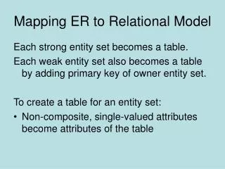
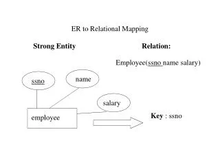
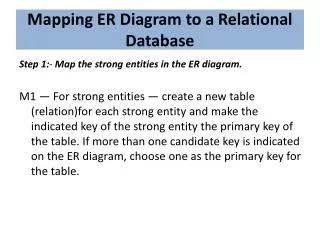
ER-to-Relational Mapping Algorithm • Step 1: Mapping of Regular Entity Types. • For each regular (strong) entity type E in the ER schema, create a relation R that includes all the simple attributes of E. • Choose one of the key attributes of E as the primary key for R. If the chosen key of E is composite, the set of simple attributes that form it will together form the primary key of R. Example: We create the relations EMPLOYEE, DEPARTMENT, and PROJECT in the relational schema corresponding to the regular entities in the ER diagram. SSN, DNUMBER, and PNUMBER are the primary keys for the relations EMPLOYEE, DEPARTMENT, and PROJECT as shown.
ER-to-Relational Mapping Algorithm (cont) • Step 2: Mapping of Weak Entity Types • For each weak entity type W in the ER schema with owner entity type E, create a relation R and include all simple attributes (or simple components of composite attributes) of W as attributes of R. • In addition, include as foreign key attributes of R the primary key attribute(s) of the relation(s) that correspond to the owner entity type(s). • The primary key of R is the combination of the primary key(s) of the owner(s) and the partial key of the weak entity type W, if any.
Step 2: Mapping of Weak Entity Types Example: Create the relation DEPENDENT in this step to correspond to the weak entity type DEPENDENT. Include the primary key SSN of the EMPLOYEE relation as a foreign key attribute of DEPENDENT (renamed to ESSN). The primary key of the DEPENDENT relation is the combination {ESSN, DEPENDENT_NAME} because DEPENDENT_NAME is the partial key of DEPENDENT.
ER-to-Relational Mapping Algorithm (cont) • Step 3: Mapping of Binary 1:1 Relation Types For each binary 1:1 relationship type R in the ER schema, identify the relations S and T that correspond to the entity types participating in R. There are three possible approaches: (1) Foreign Key approach: Choose one of the relations-S, say-and include a foreign key in S the primary key of T. It is better to choose an entity type with total participation in R in the role of S. Example: 1:1 relation MANAGES is mapped by choosing the participating entity type DEPARTMENT to serve in the role of S, because its participation in the MANAGES relationship type is total. (2) Merged relation option: An alternate mapping of a 1:1 relationship type is possible by merging the two entity types and the relationship into a single relation. This may be appropriate when bothparticipations are total. (3) Cross-reference or relationship relation option: The third alternative is to set up a third relation R for the purpose of cross-referencing the primary keys of the two relations S and T representing the entity types.
ER-to-Relational Mapping Algorithm (cont) • Step 4: Mapping of Binary 1:N Relationship Types. • For each regular binary 1:N relationship type R, identify the relation S that represent the participating entity type at the N-side of the relationship type. • Include as foreign key in S the primary key of the relation T that represents the other entity type participating in R. • Include any simple attributes of the 1:N relation type as attributes of S. Example: 1:N relationship types WORKS_FOR, CONTROLS, and SUPERVISION in the figure. For WORKS_FOR we include the primary key DNUMBER of the DEPARTMENT relation as foreign key in the EMPLOYEE relation and call it DNO. N is reflected by n records sharing the same 1 in R.
ER-to-Relational Mapping Algorithm (cont) • Step 5: Mapping of Binary M:N Relationship Types. • For each regular binary M:N relationship type R, create a new relation S to represent R. • Include as foreign key attributes in S the primary keys of the relations that represent the participating entity types; their combination will form the primary key of S. • Also include any simple attributes of the M:N relationship type (or simple components of composite attributes) as attributes of S. Example: The M:N relationship type WORKS_ON from the ER diagram is mapped by creating a relation WORKS_ON in the relational database schema. The primary keys of the PROJECT and EMPLOYEE relations are included as foreign keys in WORKS_ON and renamed PNO and ESSN, respectively. Attribute HOURS in WORKS_ON represents the HOURS attribute of the relation type. The primary key of the WORKS_ON relation is the combination of the foreign key attributes {ESSN, PNO}.
ER-to-Relational Mapping Algorithm (cont) • Step 6: Mapping of Multivalued attributes. • For each multivalued attribute A, create a new relation R. This relation R will include an attribute corresponding to A, plus the primary key attribute K-as a foreign key in R-of the relation that represents the entity type of relationship type that has A as an attribute. • The primary key of R is the combination of A and K. If the multivalued attribute is composite, we include its simple components. Example: The relation DEPT_LOCATIONS is created. The attribute DLOCATION represents the multivalued attribute LOCATIONS of DEPARTMENT, while DNUMBER-as foreign key-represents the primary key of the DEPARTMENT relation. The primary key of R is the combination of {DNUMBER, DLOCATION}.
ER-to-Relational Mapping Algorithm (cont) • Step 7: Mapping of N-ary Relationship Types. • For each n-ary relationship type R, where n>2, create a new relationship S to represent R. • Include as foreign key attributes in S the primary keys of the relations that represent the participating entity types. • Also include any simple attributes of the n-ary relationship type (or simple components of composite attributes) as attributes of S. Example: The relationship type SUPPY in the ER below. This can be mapped to the relation SUPPLY shown in the relational schema, whose primary key is the combination of the three foreign keys {SNAME, PARTNO, PROJNAME}
Summary of Mapping constructs and constraints Correspondence between ER and Relational Models ER Model Relational Model Entity type “Entity” relation 1:1 or 1:N relationship type Foreign key (or “relationship” relation) M:N relationship type “Relationship” relation and two foreign keys n-ary relationship type “Relationship” relation and n foreign keys Simple attribute Attribute Composite attribute Set of simple component attributes Multivalued attribute Relation and foreign key Value set Domain Key attribute Primary (or secondary) key, or unique attribute
ER modeling concepts are sufficient for representing simple database application. • To deal with databases with more complex requirements, additional data modeling techniques have been proposed. • One of them is the enhanced ER, i.e., EER.
Enhanced-ER (EER) Model Concepts • Includes all modeling concepts of basic ER • Additional concepts: subclasses/superclasses, specialization/generalization, categories, attribute inheritance • The resulting model is called the enhanced-ER or Extended ER (E2R or EER) model • It is used to model applications more completely and accurately if needed • It includes some object-oriented concepts, such as inheritance
Enhanced mapping • There are additional rules about how to map EER Model Constructs to Relations.