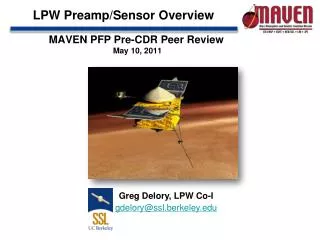
LPW Preamp/Sensor Overview
MAVEN PFP Pre-CDR Peer Review May 10 , 2011. LPW Preamp/Sensor Overview. Greg Delory, LPW Co-I gdelory@ssl.berkeley.edu. Overview. LPW sensor consists of: Preamp: analog circuitry for current and voltage measurements Whip: antenna used by the preamp LPW preamp design based on:

LPW Preamp/Sensor Overview
E N D
Presentation Transcript
MAVEN PFP Pre-CDR Peer ReviewMay10, 2011 LPW Preamp/Sensor Overview Greg Delory, LPW Co-I gdelory@ssl.berkeley.edu
Overview • LPW sensor consists of: • Preamp: analog circuitry for current and voltage measurements • Whip: antenna used by the preamp • LPW preamp design based on: • FAST (relays, switching from voltage to current mode) • THEMIS (similar/identical op-amps, temperature requirements) • LPW preamp is: • Similar to THEMIS for temperature requirements • Less than THEMIS for radiation requirements • Lower in complexity than FAST preamp
LPW Sensor Design • Whip – an antenna, a conductor through which voltage and current in the plasma are measured • Needs to be of sufficient size for high coupling capacitance and current collection area • Requires coating for chemical/structural durability and surface uniformity (Titanium Nitride) • Stub, Guard – each biased at a controlled voltage depending on measurement mode • Mitigates photoelectron effects in voltage mode, end effects in current mode • Preamp enclosure – houses preamplifier electronics at the base of the whip antenna. • High impedance interface to the plasma / buffer for driving boom cable Whip – 50 x 0.635 cm “Stub” “Guard” Preamp Enclosure
Preamp – Since PDR • No major changes • Decisions made for critical active/unique parts (see next slides) • Added Whip guard to reduce input capacitance of final sensor assembly • Comprehensive measurement and test program
Sensor Tests: Voltage Mode Resistive Coupling Capacitive Coupling Input Capacitance = 13 pF 2m cal chamber 1 Meg/chamber capacitive coupling
Assembled EM Unit EM Whip, preamp, boom, harness in RBSP-derived cal chamber. Test stimulus delivered through coupler block
Assembled EM Unit DFB/BEB External power supplies MISG
Current Status Summary • Few changes from PDR • EM Sensor, boom fabrication and assembly complete • LPW Whips fabricated, and currently out for coating • Tests of integrated preamp/sensor assembly yielded no surprises • First tests with complete EM system conducted • No major anomalies, but more analysis needs to be done • Electronics boards back at LASP – will continue testing boom/sensor combination here @ SSL
Work Remaining for CDR/FM Build • Relay Life Test • Happening now • Preamp Qualification Model (QM) • Flight-quality board, low CTE Arlon 85NT construction • Used to verify temperature predicts (~-170 to +80 C) • Integrated EM system test: • Understand details of instrument response • Perform complete calibration
Parts Selection (1) • Voltage mode op-amp: • Candidates at PDR were OP-16A, OP-15A • Chose OP-16A due to superior frequency response • Similarity with OP-15A = confidence it will pass qualification • OP-15A remains a valid, swap-in backup • Current mode op-amp: • Candidates at PDR were AD-549 and OP-15A • Chose OP-15A satisfies measurement requirements – chosen due to reliability history • AD-549 has superior sensitivity, but less heritage • Teledyne 422DD Latching Relay • Same as PDR. Heritage from FAST • Undergoing life tests now (several million cycles)
Parts Selection (2) • DT-471 Temperature sensor • Same as PDR • Tested in benchtop environment • 50M surface mount chip resistor • Special order from SOTA • Same basic specification/design as 75M resistor used in RBSP • Remaining components are standard passives
Preamp Voltage Mode Results Resistive Coupling Capacitive Coupling Benchtop Preamp Tests 1 Meg/3.3 pF coupling Board Input Capacitance = 9 pF
Current Mode Tests Simulate voltage, current, and coupling impedance encountered in different measurement regimes. 1. Pick point on simulated V-I curve 2. Corresponding point on impedance curve • Verified sensitivity from ~nA to 200 uA levels • Instability noted at high coupling impedances • Verified and mitigated through stability analysis (22 pF lead cap)
Whip Coating • TiN – Titanium Nitride • Required for chemical durability (atomic oxygen resistance) • Work function uniformity (ensures accurate Ne, Te measurements) • Has significant heritage • Cassini (IRF/Iowa 1997 - , Saturn), Astrid-2 (1998 - 1999, Earth’s ionosphere) • Cusp (NASA 35.033 sounding rocket, GSFC 2002) • Rosetta (IRF 2004 - , comet) • Demeter (CNRS/ESTEC 2004 - , Earth’s ionosphere) • Swarm (IRF 2011 - , Earth’s ionosphere)
Whip Coating (2) • Previous TiN applications have been tested for uniformity and durability (Wahlström, 1992; Steigies, 2005) (SEM, electrical tests, others…) Result after Nitriding illustrated by cross section of structure after Nitriding of titanium and Ti-6Al-4V, respectively (Scanning Electron Microscopy) A=fine grained TiN, B= Ti2N, C=Mixed phases, D=bulk material+nitrogen (increased hardness), E=Bulk material, F= β-phase.