Download
1 / 100
1.03k likes | 1.33k Views
PhD Course. TOPICS IN (NANO) BIOTECHNOLOGY Nanoscale Imaging and Nanoparticles. January 15th, 2007. Nanoscale Imaging. SEM TEM Scanning Probe Microscopy Scanning tunnelling microscopy Atomic force microscopy Others. Field Ion Microscope.

E N D
PhD Course TOPICS IN (NANO) BIOTECHNOLOGY Nanoscale Imaging and Nanoparticles January 15th, 2007
Nanoscale Imaging SEM TEM Scanning Probe Microscopy Scanning tunnelling microscopy Atomic force microscopy Others
Field Ion Microscope • First instrument providing images of atoms. • Principle of operation is field ionisation (closely related to field emission). • An imaging gas is introduced, these gas atoms approach the emitter, hop about until they are accommodated to the emitter temperature and are then ionised in the high-field regions above protruding atoms. • These ionised atoms then fly along the field lines and produce spots on the fluorescent screen corresponding to the protruding emitter atom.
Field Ion Microscope FEM & FIM are only useful for samples which can be formed into very sharp tips.
http://idol.union.edu/~malekis/ESC24/Seyffie's%20Pages/Imaging/Imaging.htmhttp://idol.union.edu/~malekis/ESC24/Seyffie's%20Pages/Imaging/Imaging.htm
Transmission Electron Microscope • Specimens for examination under the transmission electron microscope (TEM) must be specially prepared to a thickness that permits the passage of electrons (50-500 nm). As the wavelength of electrons is much smaller than that of light, the resolution attainable in TEM images is many orders of magnitude better than that of a light microscope. Transmission electron microscopes can reveal the finest internal details of a cell. • For biological samples, cell structure and morphology is commonly determined whilst the localisation of antigens or other specific components within cells is readily undertaken using specialised preparative techniques. • Atomic resolution possible
Flu Virus Paramyxovirus Collagen Fibres Herpes Virus Transmission Electron Microscopy
Scanning Electron Microscope • By scanning an electron beam across a specimen and collecting electrons emitted from the irradiated spot we can obtain topographical and chemical information on materials from the macroscopic scale to very high magnifications with great depth of field in focus. • Resolution ~1 nm.
Hibiscus Pollen Holm Oak Leaf Penicillin Spores Mosquito Antennae Scanning Electron Microscopy Beetles Skin
Scanning Probe Microscopy • Scanning Tunnelling Microscopy • Atomic Force Microscopy • Others
Scanning Probe Microscopes • SPMs are a family of instruments used for studying properties of materials from the atomic to the micron level.
Scanning Tunnelling Microscopy • Invented 1981 (Binnig & Rohrer) • Use sharpened, conducting tip with a bias voltage applied between the tip and the sample. • Within ~1 nm of the sample, electrons tunnel between the tip and the sample (direction depending on the sign of the bias voltage). • This tunnelling current varies exponentially with the tip-to-sample spacing. • Tip and sample must be conductors or semiconductors (cannot image insulating materials). • Measures a surface of constant tunnelling probability (not the physical topography!)
Scanning Tunnelling Microscopy http://www.iap.tuwien.ac.at/www/surface/STM_Gallery/stm_animated.gif
Scanning Tunnelling Microscopy Sub-angstrom vertical & atomic lateral resolution.
Scanning Tunnelling Microscopy Imaging Modes • Constant Height • Fast • Only useful for smooth surfaces • Constant Current • Slower • Good for irregular surfaces
Atomic Force Microscopy • An AFM probes the surface of a sample with a sharp tip. Tip located at the free end of cantilever that is 100-200 m long. • Forces between the tip and cantilever cause the cantilever to bend and/or twist. • This deflection is measured as the tip is scanned over the surface, providing a map of the surface topography. • AFMs can be used to study insulators and conductors. • AFMs can be operated in air, vacuum, and in liquids. Biological measurements, in particular, are often carried out in vitro in biological fluids.
0.1 mm Atomic Force Microscopy • Common detection schemes • Optical lever • Optical interference • Piezoelectric effect • …
Atomic Force Microscopy Interaction Forces • Van der Waals • Contact mode • Close • Repulsive • Non-contact mode • 1’s – 10’s of nm tip - sample separation • Attractive http://www.cookandkaye.co.uk/products/cfm.html F = 0 @ ~0.2nm (length of chemical bond)
Contact (Repulsive) Mode AFM • AFM tip makes soft physical contact with the sample. • Contact force causes the cantilever to bend to accommodate changes in topography. • Cantilever spring constant less than effective spring constant holding atoms together in sample. • F ~ 10-7 – 10-6 N
Non-Contact (Attractive) Mode • Vibrating stiff cantilever (100 – 400 Hz) • Amplitude 1’s – 10’s nm • Spacing 1’s – 10’s nm • Total force ~10-12 N • Detect changes in frequency or amplitude of the cantilever caused by changes in the force gradient (slope of force-distance curve). • Height resolution better than 0.1nm • Good for soft and/or elastic samples • No contamination of sample by tip
Contact vs Non-Contact Mode Comparison • Non-Contact • Low damage • Less sensitive to fine topographical detail • Contact • Can damage soft samples through lateral forces (dragging material)
150150 m2 300nm Contact Mode AFM Images
Tapping Mode AFM • Similar to non-contact mode, but at bottom of travel the tip just ‘taps’ the sample surface • Oscillation amplitude is monitored • Eliminates lateral forces (friction /drag) • Excellent for soft samples (e.g. biological samples, LB films, etc.) • Tapping Mode overcomes problems associated with friction, adhesion, and electrostatic forces
AFM in the Life Sciences • Fundamental Challenges of Microscopy in Biology: • to preserve the specimen accurately in the native state • to achieve sufficient resolution to learn something useful about the structure/function of the specimen • AFM is a breakthrough technology that allows three-dimensional imaging and measurement of unstained and uncoated structures in air or fluid from molecular to micron scales • scanners can now be immersed in liquids without damage, allowing direct examination of samples in biological fluids, water, or fixation media such as glutaraldehyde or ethanol
AFM in the Life Sciences • In addition to topographic imaging, the AFM can be used simultaneously to measure forces on active biological specimens, offering insight into cellular and even molecular dynamics. • Countless biological processes - muscle contraction, cell motility, DNA replication, protein synthesis, drug-receptor interactions, and many others - are largely governed by intermolecular forces. And with its sensitivity at the piconewton-level, the AFM is an excellent tool for probing such interactions. • There is increasing use of AFM probes that have been chemically tailored to sense a specific biological reaction or interaction (e.g. binding forces between individual ligand-receptor pairs, cell adhesion, antibody or DNA-based assays).
Tapping Mode AFM in Biology E-coli erythrocyles
Tapping Mode AFM in Biology Successive tapping mode images under liquid of living endothelial cells (scan size 70 microns) Collagen fibres • Human Bone • (collagen fibers & hydroxyapatite crystals) • Dynamics of Protein Adsorption • (lysozyme on a new contact lens over time) http://virtual.itg.uiuc.edu/training/AFM_tutorial/
Lateral Force Microscopy • LFM measures the lateral deflections (twisting) of the cantilever parallel to the plane of the sample surface • Useful for imaging e.g. composition variations not associated with topography, and for separating topographic and composition variations. • Also sensitive to changes in the surface slope. • Usually collect both AFM and LFM images simultaneously.
scan direction scan direction 1 m 1m step 22 m2 0.40.4 m2 0.40.4 m2 LFM Images
Overview • Definition and Significance • Synthesis and Characterization • Stabilization • Ordering • Optical Properties • Magnetic Properties • Catalysis
Significance The size of Nanoparticles leads to unique characteristics. Definitions Nanoparticle - Particle with 1 dimension in the 10-100 nm size range. Colloid - Particle with dimensions in the 1 nm – 1 mm size range. Quantum Dot - Particle with all 3 dimensions in the 1-10 nm size range. Latex - Aqueous suspension of polymer particles. Natural - Contains Protein Impurities; May Cause Allergies Synthetic - Made via Emulsion Polymerization
Metallic Nanoparticle Synthesis M = Au, Pt, Ag, Pd, Co, Fe, etc. Reductant = Citrate, Borohydride, Alcohols Shipway, A.N.; Katz, E.; Willner, I. CHEMPHYSCHM. 2000, 1, 18-52.
Control Factors Average Size Reductant Concentration Stirring Rate Temperature Size Distribution Rate of Reductant Addition Stirring Rate Fresh Filtered Solutions Stabilization Solution Composition
Functionalized Reductions Shipway, A.N.; Katz, E.; Willner, I. CHEMPHYSCHM. 2000, 1, 18-52.
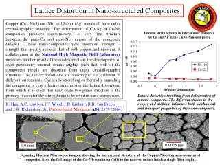
M1 M1+ + Reductant M1 M2+ + Reductant M1 + M2 M1+ + M2+ + Reductant Bimetallic Nanoparticle Core-Shell Mixed Alloy Toshima, N.; Yonezawa, T. New Journal of Chemistry1998, 1179-1201.
Alloyed Metal Nano Particles • Solid-solution alloyed metallic nano particles can be attained through simultaneous thermal decomposition • Core-shell alloyed nano particles are produced by a stepwise reduction process where each successive step uses larger diameter water droplet to yield the alloyed core-shell particles
R Se Se R NC Cd CN R R Se Se TOP/TOPO 200ºC PO CdSe OP OP Semiconductor nanoparticles(Q-dots) PO Nigel L. Pickett et al. The Chemical Record2001, 1, 467-479
Synthesis of Single Metal MNPThe Reduction of Metal Salts • Size control: conducting the reaction in a confined reactor • Nano confined reactor such as water-in-oil or oil-in-water micro-emulsion system • Size of confined space can be defined by varying amount of both surfactant and solvent • Successful examples included Fe, Ni and Co particles
Organic Nanoparticles Dieter Horn et al. Angew. Chem. Int. Ed 2001, 40, 4330-4361 Organic compound + Lipophilic solvent Water + Stabilizer Emulsification Hydrosol of organic compound Separation of solvent
Micelle formed from emulsifier Monomer Polymer Stability Sphere Polymer Nanoparticle Synthesis Initiator