Download
1 / 20
210 likes | 399 Views
Mini-Thermosyphon Test Results. Jose Direito et. al. (EN/CV/Detector Cooling). Objectives/Motivations. Validation of the Thermosyphon concept in a smaller scale (17.4 meters of height). Report the behavior of system during Start up/operation/shut down.

E N D
Mini-Thermosyphon Test Results Jose Direito et. al. (EN/CV/Detector Cooling) Mini-Thermosyphon Tests Results
Objectives/Motivations • Validation of the Thermosyphon concept in a smaller scale (17.4 meters of height). • Report the behavior of system during Start up/operation/shut down. • Gain experience on the operation of the plant. Mini-Thermosyphon Tests Results
General Scheme and Layout @ Blg 191 Condenser • Natural circulation of the Fluid (C3F8) • On the liquid phase by gravity • On the gas phase by pressure difference P1 Chiller ΔH P2 > P3 > P1 Liquid Gas ~18m P3 P2 Dummy Load Detector/Evaporator Mini-Thermosyphon Tests Results
Thermodynamic Cycle C3F8 Pressure – Enthalpy Diagram Start-up A-B : Condensation and sub-cooling B-C : Hydrostatic ΔP C-D : Expansion D-E : Evaporation and super heating Liquid Ramp Down Running Cold Gas 2-Phase Mini-Thermosyphon Tests Results
Mini-Thermosyphon Working Principles Calc. Saturation Temperature C6F14 circuit C3F8 • Conditions to run: • Condenser Sat. Temp. > Liq. Temp. • Liq. Pressure (supply line) > Local Sat. Pressure • Outlet Vapour Temp. > Evap. Temp. • Monitored Parameters: • ΔT = Tsaturation – Tliquid • ΔP = Psupply – Psaturation(and/or Tsaturation (local) – Tlocal) • ΔT = Tout gas – Tevaporation • Possible Set Points: • Chiller Set Point (sets the Cond./Evap. Temp.) • Expansion Valve (sets the flow) • Dummy Load Outlet Temperature FT PT Mini-Thermosyphon Tests Results
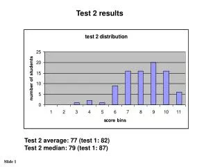
Stable Running Conditions Evaporation temperature of -5°C Flow = 30g/s (3kW) Condenser pressure oscillations of 23mbar Evaporation Temperature oscillations of 0.15°C Evaporation temperature of -25°C Flow = 21g/s (2.1kW) Condenser oscillations of 28mbar Temperature oscillations of 0.4°C (oscillations can be reduced by installing a pressure regulator) Mini-Thermosyphon Tests Results
35 hours Run Mass Flow of 16g/s (1.6kW of Cooling Power); Evaporating at -28°C Mini-Thermosyphon Tests Results
Running Conditions at different Temperature and Flow rates T gas • Decreasing the flow from 30 to 15g/s: • Higher efficiency on the condensation -> lower evaporation temperatures • The chiller set point should be related to the condenser saturation temperature. Tsat Chiller T liq C6F14 Treadout chiller Mini-Thermosyphon Tests Results
Starting up and Ramping Down 22g/s (2.2kW cooling power) – 3:35 hr to go from 25°C to -25°C (ΔT=50K -> 14.3K/hr) - The condensation on the tank is faster than the sub cooling! - Having the saturation temperature close to the liquid temperature can stop the flow! Mini-Thermosyphon Tests Results
Faster Ramp Down with higher flows C3F8 flow of 30g/s (~3kW) 2:45 hours to go from 25°C to -25°C (ΔT=50K -> 18.2K/hr) Flow from 26g/s (2.6kW) to 14g/s (1.4kW) 1:05 hours to go from 25°C to -25°C (ΔT=50K -> 47.6K/hr) Mini-Thermosyphon Tests Results
Stopping examples Saturation Temperature got too close to the Liquid Temperature (very low flow) m [g/s] P [bar] T sat ≈ T liquid Mini-Thermosyphon Tests Results
Stopping examples Supply Manifold temperature (T06) higher than the local saturation temperature Mini-Thermosyphon Tests Results
System Restart after a Stop After the Stop, the Chiller Set Point was increased until the dP indicates that there is liquid on the supply line The Flow was then restarted Mini-Thermosyphon Tests Results
Optimising and Scaling the Thermosyphon • Because of the High Cost of Chillers for low temperatures: • Minimisation of the ΔT between the Chiller and the Evaporation Temperature: • ΔT between the Chiller and the Liquid part of the condenser. • ΔT between the Liquid and the Condensing part of the Condenser. • Decrease the minimum flow rate necessary to keep the plant running. Mini-Thermosyphon Tests Results
Liquid and Saturation Temperatures study T gas Tsat (Chiller Set Point) T liq Mini-Thermosyphon Tests Results
Minimisation of the ΔT on the Liquid Part: Insulation Chiller Power Heat removed from the C3F8 Pick Up Heat A Proper Insulation is required! Mini-Thermosyphon Tests Results
Minimisation of the ΔT (Liquid and Saturation Temperature) T gas • This ΔT can be minimised but there must be a minimum value to keep the plant running: • Take full advantage of the surface area on the design phase. • Changing the flow rate on the C6F14 circuit according to this ΔT on the final Plant: • If the ΔT is small then the flow should be decreased and vice versa. • This can also reduce the minimum flow required to keep the plant running. Tsat (C6F14 Flow) T liq Reduced the C6F14 Flow Mini-Thermosyphon Tests Results
Behaviour when the Chiller turned off • Stopping the chiller only: • The saturation temperature increases but it keeps running. • The rate at which the temperature increases can be reduced if the chiller pump keeps running. • Stopping the chiller and the flow: • It would be possible to restart at least 5 min later. • This time can be increased using a proper insulation. Valve closed Chiller Stopped Chiller Stopped Mini-Thermosyphon Tests Results
Pixel Stave connected to the Thermosyphon Flow rate on the Half Stave of 1.6g/s; Stave Power of 100W Tests and Results By: Vaclav Vacek, Rene Marek; Czech Technical University – Prague KirillEgorov – CERN Mini-Thermosyphon Tests Results
Conclusions • The Thermosyphon works! • Its possible to scale it for different Power, Temperature, and Fluid requirements. • It is very reliable, since no working components (pumps or compressors) exist on the plant. Mini-Thermosyphon Tests Results