Download
1 / 16
160 likes | 231 Views
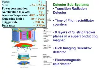
Detector systems to find HFS of 209 Bi 80+ @ ESR. Emission characteristics Counting rates at existing mirror section Straight on detector option Parabolic mirror system Outlook. Denis Anielski, Volker Hannen, Raphael Jöhren, Christian Weinheimer Westfälische Wilhelms-Universität Münster

E N D
Detector systems to find HFS of 209Bi80+ @ ESR • Emission characteristics • Counting rates at existing mirror section • Straight on detector option • Parabolic mirror system • Outlook Denis Anielski, Volker Hannen, Raphael Jöhren, Christian Weinheimer Westfälische Wilhelms-Universität Münster 02.04.2009
Relativistic Doppler Effect and Boost (β = 0.71) • Relativistic Doppler Effect λ = λ´γ(1- βcos(θ)) θ= 0° → 640nm λ´ = 1555nm θ= 40° → 1000nm • Observed angle • Boost
Simulation of Boost Polar angles in the comoving system Polar angles in the lab system (Isotropic light source) A(0°,10°) = 4% A(10°;30°) = 25% A(10°;50°) = 52% → Most photons not in straight forward direction, because of sin(θ) in solid angle!
General Assumptions • Number of excited ions: 2 e5 • Lifetime in lab system: 82 ms [1] • Lifetime in comoving system: 116 ms • QE = 10% • Circumference of ESR: 108 m • β = 0.71 [1] V. M. Shabaev, PHYSICAL REVIEW A, JAN 1998
Mirror System • 10 elliptical mirrors on a 65cm section • Original simulation software not available • First order estimate: geometric count rate estimate • Realistic simulations using GEANT4 under progress
Estimated counting rate Counting rate is proportional to • Emitted photons per second NPh = N/tau = 1,72 e6 • Ratio of totally emitted photons A = 0.38 (646 nm – 950 nm; 5°-37° ) • Loss by reflexion and transmission R*T = 1/3 (R=0.35!!!) • Quantum efficency QE = 0,1 • Relevant beam section b = 0.065m/ 108m • Geometry of mirror system g = 2/3 • Number of windows (dia: 7cm) # = 3 → f = NPh · A · g · RT · QE · b · # = 26 Hz
Straight on option • Diameter of window: 60mm • Straight beam section: 17 m • Distance – beam – detector: 3,5 m • All Photons are focused on detector by a lense • Transmission of lense: 0.9 → 0,36 Hz (simulation c++)
Parabolic mirror Detects forward emission → short wavelengths
Parabolic mirror Assumptions • Reflectivity coefficient: 0.8 • Hole in mirror with diameter of 2cm for the beam GEANT4 model www.edmundoptics.com
2-flange option • Diameter of flange for mirror: 10 cm • Diameter of flange for detector: 3.8 cm • Distance: Beam - Detektor: 30 cm • Straight section before mirror: 5 m • Radius of mirror: 5 cm • Lightguide as interface from window to detector • GEANT4 simulation (Volker Hannen) → 15 Hz
1-flange option – C++ Simulation • Diameter of flange: 20 cm • Distance: Beam - Detektor: 25 cm • Straight section before mirror: 5 m / 10 m • Radius of mirror: 7.5 cm • Radius of detector/ focussing system: 3 cm • Counting rate is multiplied by 0.9 because of slit → 45Hz / 60 Hz (Flange is just in front of mirror system!) Possible improvement with recessed exit window (distance beam – exit window = 15cm): 154 Hz
CPM beam tests • Two setups have been installed at ESR yesterday • Investigations of background photons and behaviour of CPM next to dipole magnet • Positions: • 2-flange option • Straight on option • Detectors: Channel-Photomultiplier • Easy to handle • Low dark count rate • Only 2% QE around 650nm • Suitable for 244nm transition at SPECTRAP (QE= 18%)
Conclusions • Mirror system: • 26 Hz, but dark counts of three detectors, broad wavelength range • Reflexion of mirror? • Not all three windows present • ??? • Straight on • very low rate ( < 1Hz) • ??? • Parabolic mirror • System with highest counting rate on a SINGLE detector • Small wavelengths (640 – 680nm) • !!!
Outlook • Detailed GEANT4 simulation of existing mirror system and search for best parameters of parabolic mirror system • Test of Hamamatsu R943-02 PMT (suitable detector for parabolic mirror system)