CANDU Detector Systems
CANDU Detector Systems. B. Rouben McMaster University EP 4P03/6P03 2008 Jan-Apr. 1 fast-response detector per zone compartment (+1 spare)

CANDU Detector Systems
E N D
Presentation Transcript
CANDU Detector Systems B. Rouben McMaster University EP 4P03/6P03 2008 Jan-Apr
1 fast-response detector per zone compartment (+1 spare) Bulk control: average of the 14 detector readings used as indicator of current power. Water fills in all compartments uniformly increased or decreased to move reactor power down or up to the desired power. Bulk control exercised automatically by the RRS every half second. Spatial control: individual detector readings used as indicator of zone powers. Water fills in compartments manipulated differentially to shape 3-d power distribution to target shape. Spatial control exercised automatically by the RRS every 2 seconds. Detectors give essentially “point” readings; are calibrated every 2 minutes to zone fluxes from flux-mapping system. Zone-Control Detectors
The black bars show the location of zone-control detectors(Note: Detectors are not inside compartments)
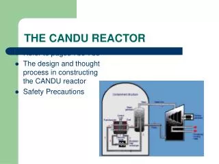
CANDU reactors are equipped with protection systems which detect an emergency situation and actuate the safety system(s). There is a separate neutronic protection system for each SDS. Each protection system is triplicated [has 3 separate “logic” (or “safety”) channels] and consists of out‑of‑core ion chambers and in‑core self‑powered detectors. Logic channels are D, E, and F for SDS-1 and G, H, and J for SDS-2. In each protection system, it suffices that 2 of 3 logic channels be “tripped” for the corresponding SDS to be actuated. Neutronic Protection Systems
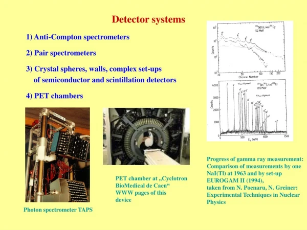
There are 3 ion chambers in each protection system, 1 per logic channel. They are located at the outside surface of the calandria (see next Figure). Each ion chamber trips its logic channel when the measured rate of change of the logarithm of the flux , i.e. the quantity d(ln )/dt, exceeds a pre‑determined setpoint (e.g. 10% per second, i.e., 0.10 s‑1, for SDS-1 in the CANDU 6). Out-of-Core Ion Chambers
There are also fast‑response (platinum or inconel) in‑core detectors in each protection system. In the CANDU 9: 54 in-core detectors for SDS-1, in vertical assemblies, and 48 for SDS-2, in horizontal assemblies (see next 2 Figures for CANDU-6 detectors). The detectors are distributed among the various logic channels: channelsD, E and F contain 11 or 12 detectors each, channelsG, H, and J contain eight each. The detectors trip the logic channels on high neutron flux: when the reading of any 1 detector reaches a pre‑determined setpoint, the logic channel to which it is connected is tripped. The in-core-detector system is known as the regional‑overpower‑protection (ROP) system. The detector trip setpoints are determined by an extensive analysis of hypothetical loss‑of‑regulation accidents. In-Core ROP Detectors
The tripping logic of each triplicated protection system is as follows (see next Figure): One ion chamber can trip its logic channel on high log rate, or any 1 detector in the logic channel can trip the channel on high flux. Any 2 tripped channels will actuate the associated shutdown system. The triplicated tripping logic reduces the chance of a spurious trip, and allows the testing of the system on-line. Triplicated Tripping Logic
The CANDU6 and CANDU 9 are provided with a flux‑mapping system to synthesize the 3‑dimensional flux distribution in the reactor from in‑core detector readings. In the CANDU 6, there are 102vanadium flux-mapping detectors (1-lp long) at various positions in the core (see next Figure). The flux‑mapping procedure is based on writing the 3-d flux distribution as a linear combination of a number of basis functions or flux modes. The mode amplitudes are determined by a least‑squares fit of the calculated fluxes at the 102 detectors to the measured fluxes. The 3-d flux distribution can then be reconstructed. The flux-mapping modes consist of 15 pre‑calculated harmonics of the neutron diffusion equation(see following Figure) and some reactivity-device modes. Flux mapping is done automatically every 2 minutes. The zone fluxes from flux mapping are used to calibrate the zone-control detectors. Flux-Mapping System
Harmonic Modes for Flux-Mapping The fundamental mode is the nominal flux shape. The other harmonics are possible global perturbation shapes of the neutron flux distribution.