Download
1 / 24
250 likes | 383 Views
Low Cost Spread-Spectrum Receiver. Senior Design Project 12-4-02 Dave Farris, Ray Maggio, Katie Sutton. Agenda. Project Description System Blueprint Project Build Test Results Benefits Conclusion. Project Description.

E N D
Low Cost Spread-Spectrum Receiver Senior Design Project 12-4-02 Dave Farris, Ray Maggio, Katie Sutton
Agenda • Project Description • System Blueprint • Project Build • Test Results • Benefits • Conclusion
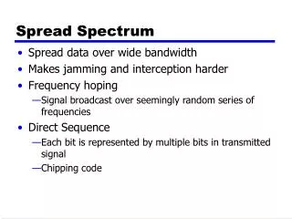
Project Description • To design a small, low-cost receiver for a spread-spectrum communication system • To simplify the receiver by using a one-bit quantizer • Resistant to high levels of unknown interference
Objective • To create a MATLAB simulation of our proposed spread-spectrum communication system • To test this system under a variety of interference conditions, and compare the results to the results of the same system without the dither block
Benefits to the End Customer • Can be implemented at a low-cost by adding a 1-bit quantizer to a basic spread-spectrum system • Secure, undetectable communication • Functions in the presence of noise • Able to withstand a range of unknown interference
Applications • Customers seeking simpler implementation spread-spectrum receiver • Cellular phones • 2.4 GHz Cordless phone • Customers seeking resistance to multiple types of intentional, unknown interference • Military • Security Firms • Banks
Product Features • Spread Spectrum technology • Unique dither algorithm to offset the effects of noise and interference • One-bit quantizer • Comparable performance to a system using a multi-bit quantizer, up to 15 dB interference powers • Processing gain >= 1000
Channel Input X X Code Generator Code Generator Matched Filter Output Transmitter Receiver Basic Spread Spectrum System • Input: A binary data file • Code Generator: A special sequence, called the spreading code is created to encrypt the signal. • Transmitter: The transmitter multiplies the input and the code, creating the spread-spectrum signal.
Channel Input X X Code Generator Code Generator Matched Filter Output Transmitter Receiver Basic Spread-Spectrum System cont. • Channel: The spread-spectrum signal is transmitted over a channel containing interference. • Code Generator: Uses same code as transmitter to decrypt signal • Matched Filter: There are several filter designs to take the decrypted code and turn it into a digital sequence. • Output: A binary data file
Channel Matched Filter Input Limiter X X + Measure Interference Power Generate Dither Code Generator Code Generator Output Transmitter Dither Block Receiver System with Added Dither Block • Measure Interference Power: Measures an average interference power over k samples • Generate Dither: Uses the average interference power value to generate a dither signal to add to the received signal • Limiter: Decides either 1 or -1 based on the polarity of the signal
System Implementation • Transmitter • Mapped an input signal and PN code to 1’s and -1’s • Multiplied input signal and code • Channel • Interference samples added to the transmitted signal • Two interference shapes: Gaussian and Rectangular Wave • Receiver • Multiply signal from channel/dither block by PN code • Use Integrate and Dump filter over the period of the code length (1023) to receive binary data signal
Dither Block Algorithm One • Interference Power Estimator • Stores k samples to estimate interference power • Uses estimate to choose magnitude of dither • Dither Adder: Adds dither to the received signal according to uniform distribution • Limiter: Decides either 1 or -1 based on the polarity of the input
Dither Block Algorithm Two • Takes into account the polarity of each bit it receives, in addition to the magnitude • Magnitude of Interference Power calculated using the same as in first dither algorithm • Dither is added back into the signal, bit by bit, with the sign determined by the received polarity
Testing • Test cases: 1. Control (no dither, no limiting) 2. Limiting without dither 3. Limiting with dither • Each case tested for a range of Gaussian interference, then Rectangular wave interference • Each case tested with at least 10^4 data bits
Successes • Implemented basic spread spectrum system in MATLAB • Designed two separate dither algorithms • Measured performance of dither block for different conditions • Proved reliable performance for data communication (Probability of Error< 10-4) • Verified operating range of interference powers up to 15 dB
Challenges • Test duration • Each data point required 10^8 bits to be processed • Over 10 Billion bits run through dither block • Limited by processing power/memory • Improved with optimization • Restricted us from examining performance for small interference powers • Complexity • Learning about spread spectrum communication • Researching the problem
Future Development • Design hardware implementation • Use standard spread-spectrum hardware, with added dither block • Include Error Correcting Code scheme to reduce the probability of error • Field test hardware implementation
Transition to Hardware • Transmitter: simple modulator/multiplier • Code Generator: shift register, adder • Dither Block: • Interference Power Estimator: A/D converter, storage block, and an arithmetic unit • Dither Generator: Distributions will be stored and then read from memory • Receiver: Shift registers, logic, summer
Benefits to this System • Less Complex: Proved that a simpler/cheaper digital matched filter could be used in the basic system to tolerate interference. • Interference suppression and security: Processing Gain of over 1000 yields reliable, secure communication • Robust to multiple types of unknown interference: Gaussian and Rectangular Wave
Benefits cont. • Comparable Performance to more complex system: Probability of error less than 10-4 for interference powers from 0 dB up to 15 dB • More Resistance to interference capture: A lower probability of error than the more complex system in the presence of high levels of rectangular wave interference.
Conclusion • Accomplished project goals: • Implemented spread-spectrum communication system using dither block and limiter • Verified reliable performance • System ready for transition to hardware