Development of a Programmable Proportional Flush Valve for Diverse Toilet Designs
The project focuses on designing a programmable proportional flush valve that accommodates different toilet designs by allowing controllable flow curves. Traditional flush valves typically provide a single flow characteristic, which limits efficiency across various toilet models. The new valve will operate under 10 seconds, utilize 0.5-6 liters of potable water, withstand 125 psi input pressure, and achieve a lifespan of 250,000 flushes while ensuring minimal power consumption. Compliance with Canadian Standards Association standards and adaptability to numerous design specifications are key objectives.

Development of a Programmable Proportional Flush Valve for Diverse Toilet Designs
E N D
Presentation Transcript
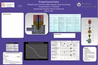
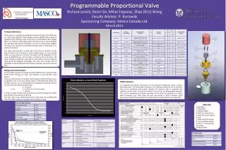
Programmable Proportional ValveRichard Levick, Kevin Sin, Milan Tepavac, Zhao (Eric) WangFaculty Advisor: P. KurowskiSponsoring Company: Masco Canada Ltd.March 2012 Company Logo here Problem Definition: Flush valves in use today are designed to have one flow curve (flow rate vs. cycle time). Different toilet designs require different flow curves to maximize their efficiency. Due to this lack of standardized toilet design, there is a need for a flush valve where the flow curve can be controlled. This will allow the valve to be flexible in its use for varying toilet designs. The flow curve should be controllable through either a mechanical or an electronic interface. The valve must operate in a cycle time of less than 10 seconds, and be able to flush from 0.5-6 litres of clean potable water. It must operate under an input pressure of 125 psi. The valve must be designed for a life cycle of 250000 flushes, and consume a minimal amount of power. The water flowing through the valve will be chlorinated, and the materials used should be designed accordingly. The valve must comply with all applicable Canadian Standards Association standards, and all at minimum cost. Background Information: • Current valves operate by creating a pressure difference on opposite sides of the orifice, forcing it to open. The limitation is only one flow curve results. • There are many factors to consider when trying to control the flow curve. A significant one is the area of flow, which is determined by orifice size.Another, velocity, can be manipulatedbychanging the diameter. We can see this from the following relationship: • Q – Flow Rate • Q = Au A – Surface Area (Orifice Diameter) • u – Velocity • In order to create the flow rate we need, we can either change the surface area of flow or the velocity of the flow. • The flow curve is also determined by the cycle time, by controlling the time the orifice is open, we can generate a variety of curves. FMEA Analysis: • It is apparent the highest risk factors are the fasteners holding the motor in place, becoming loose. The other high risk factors are indirectly caused by this occurrence. This can be eliminated with proper selection of fasteners, able to withstand the vibrations of the motor. A medium risk factor is the motor not being aligned properly. This can be eliminated with proper assembly of the motor, by allowing it to center before fastening. Our valve does not pose any threat of injury, however could potentially violate CSA standards if illicit chemicals are introduced into the water flow. Parts List: • 1: Diaphram • 2: Body Block • 3: Stepper Motor • 4: M4 Truss Head Screw • 5: Machine Screw Hex Nut • 6: Seal • 7: Motor Shaft End Piece • 8: 3.5mm Gasket Washer • 9: M4 x 0.7 Lock Hex Nut • 10: Casing • 11: Motor Shaft