Download
1 / 66
790 likes | 1.46k Views
STATNAMIC LOAD TESTING Development, Interpretation of Results, Advantages. Presentation Outline. Pile Load Testing - background Brief Statnamic Introduction Recent activities in the US Statnamic Theory and Analysis Recent activities in Taiwan 20MN testing at the TFC project, Taiwan

E N D
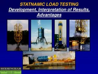
STATNAMIC LOAD TESTING Development, Interpretation of Results, Advantages
Presentation Outline • Pile Load Testing - background • Brief Statnamic Introduction • Recent activities in the US • Statnamic Theory and Analysis • Recent activities in Taiwan • 20MN testing at the TFC project, Taiwan • other notable jobs • Standardisation of “RAPID” Load Testing • Q&A and Discussion
Quick Statnamic Facts • 21 Statnamic devices world-wide • 12 Statnamic testing companies • Over 1200 contract Statnamic load tests performed in 16 countries - more than one test every day, somewhere in the world! • Over 80 published papers, including papers from 2 International Statnamic Seminars • More than 10 Universities currently researching Statnamic (USA - Auburn, USF, BYU, Umass, John Hopkins, plus others) • Acceptance by 16 State DOT’s in the US, US Army Corps of Engineers, FHWA, and Japanese Geotechnical Society
Pile Load Testing Background
The Idea Statnamic Note: The JGS defines a Rapid Load Test as 5 < tr < 500, where tr is the number of times a stress wave will travel up and down the pile during the loading event
This type of test was clearly different from a Dynamic Load TestA NEW WORD WAS REQUIRED!! • Inertial Load Testing (Bermingham - 1987) • STATNAMIC(Middendorp - (1989)) • Pseudo-static (Fundex PS PLT - early 1990’s) • Kinetic (Holeyman - 1992) • Rapid Load Test (Japanese Study Group - 1995) • Transient Long-period (Janes -1997) • Slow dynamic (Goble, Rausche - 2000) • others - impulse, kinematic, push, etc.
...a global perspective... In March of 2000, the Japanese Geotechnical Society added “Rapid Load Testing” to their national standard for pile testing. In the year 2000, it is estimated that there will be more than 500 Statnamic Load Tests on foundations around the world.
1800 tonTest Pile as Support PileMechanical Catching Mechanism
Recent Activities in the USA Use of Water as Reaction Mass
Recent Activities in the USA Lateral Load Testing
Lateral Test Programs in the US • New Bern, North Carolina DOT (50 tons) • Brigham Young University - (200 tons) Utah DOT & CALTRANS • Auburn University, Alabama - (250 tons) (FHWA) • Pascagoula, Mississippi DOT (800 tons, over-water) • Providence, Rhode Island DOT (400 tons, over-water) • San Juan, Puerto Rico Trans Authority (400 tons) • New Bern, North Carolina DOT (1200 tons, over-water)
“Statnamic” Earthquake Generator(John Hopkins University & FHWA)
Foundation Types Tested in the USA Using Statnamic • Drilled Shafts • tested up to 3500 tons • laterally and axially • Driven Piles (all types) • Pile Groups • tested laterally and axially • Stone Columns • Auger-Cast Piles • conventional and ‘displacement’ types • Spread Footings and Plates • Other types of “Ground Modification”
BackgroundStatnamic Theory and Analysis • GOAL: • to derive the STATIC load displacement behavior from a STATNAMIC load test • (usual goal for axial compression testing)
Structural Analogy u u m F m k k F = ku (Static) F = ma + cv + ku (Statnamic) Static Dynamic F
F u m k c Physical Model EQUATION OF MOTION: This equation describes the equilibrium between some forcing function and the 3 forces: Inertia(mass x acceleration) Damping(damping coefficient x velocity) Stiffness (stiffness coefficient x displ.) This equation forms the basis for describing the motion of any single degree of freedom system. F =ma+cv+ku
Analysis Assuming that stress-waves can be ignored, the analysis of a Statnamic Load Test is greatly simplified in comparison to a dynamic load test. Although stress-waves may be ignored, the ‘dynamic’ effects of INERTIA and DAMPING CANNOT! Result: a detailed model, which includes pile and soil properties IS NOT NEEDED. A simple physical model can be used to remove the effects of damping and inertia from the measured signals - no information about the soil is needed, and subjective judgement is minimized.
Measured Statnamic Derived Static ”Derived Static” from Statnamic
Static - 3 cycles Statnamic 14 m Driven Concrete Pile in Sand
Recent Activities in Taiwan 2000 ton Testing at the Taipei FinancialCenter