Embedded Passive Components in Circuit Boards
Embedded Passive Components in Circuit Boards Sponsored By UNISYS Corp. Mentor: Jesse Ibaibarriaga Ken Reilich Team Members Victor Kohr Emmanuel Okonta Wing Ho Lam Roland Pang Agenda Overview Gantt Chart Equivalent CKTs for Embedded Passives Simulation Cost Preview Conclusion

Embedded Passive Components in Circuit Boards
E N D
Presentation Transcript
Embedded Passive Components in Circuit Boards Sponsored By UNISYS Corp. Mentor: Jesse Ibaibarriaga Ken Reilich
Team Members Victor Kohr Emmanuel Okonta Wing Ho Lam Roland Pang
Agenda • Overview • Gantt Chart • Equivalent CKTs for Embedded Passives • Simulation • Cost Preview • Conclusion
Overview • Analysis of Embedded Passives in comparison to Surface mount Technology in terms of: • Electrical Performance • Manufacturing Costs • PCB Real Estate Savings
Equivalent circuit model for Embedded Resistor Full equivalent circuits for the embedded resistors Reduced equivalent circuits for the embedded resistors
Simulation • Tools: Sigrity Speed 2000 • Assumptions Made at this Point • Both Discrete and Embedded Passives have same Equivalent Model • One Simple Resistor or Capacitor to Replace the Full Equivalent CKT • Only the Length of Interconnects Affects Performance
One Pack of Integrated Resister Length Approx.~0.1387 inches Width Approx.~0.1704 inches Length* Width = 0.1387* 0.1704 = .023634 inches2 Total surface area is 14.15*7.8 =110.37 inches2 So 110.37/0.23634 ~ 466 of Integrated Resistor can be placed using Surface Mount Technology (SMT)
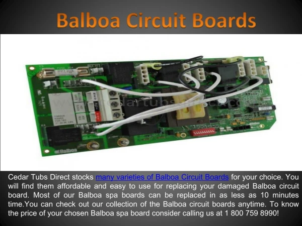
Embedded Resistor Ohmega-Ply thin-film resistor • Total board area= 110.37 inches2 • Assumption: • Half of the layer can be used due to • spacing needed among the embedded • resistors • Sheet Resistance = 25 ohms/square • 1 square = 20 micro inch • 1 pack = 8 squares • Total # of Resistors that can be embedded: • 110.37 / (2*(20*(10-3)2)*8) ~ 17245 packs (466 for SMT)
SMT Capacitor Length Approx.~0.1 inches Width Approx.~0.1574 inches Length* Width = 0.1* 0.1574 = .01574 inches2 Total surface area is 14.15*7.8 =110.37 inches2 So 110.37/0.1574 ~ 701 of capacitor can be placed on the surface. Total Capacitance = 701*100pF = 70.1nF
Embedded Capacitor Assumptions: • Sanmina-sci ZBC-2000 is used • Capacitance = 0.5nF/in2 • Whole layer can be used Total capacitance = 110.34in2* 0.5nF/in2 = 55.17nF < SMT(70.1nF)
COST ANALYSIS Estimates For Some Embedded Passives 73% savings,for embedding R in digital application. 27% savings, for embedding L and C in RF application
Cost Dependent Application-specifics Decreased board area(reduced discrete passives) Decreased wiring density requirement,due to integration of R&C into the Board. Increased wiring density due to decreased board size. Increased board cost/unit area. Decreased assembly cost. Increased overall assembly yield. Decreased assembly-level rework.
Key Aspects of Modeling Embedded Passive Cost1Board Size & Routine Calculations Where S is minimum assembly spacing Li and Wi are length and width of the ith discrete passive N is all discrete passives that where converted to embedded passives Acon is the conventional board area and Anew is the new board that calculated after embedding the passive components
Comparison of Profit Margin Between Conventional Board and Integrated Passives Board
Breaking Point For embedded Passive Components From the Above graph we can see that embedding 100% will not be feasible as Law of Diminishing Return will take a toll on our design. We are still working to find a breaking point where embedding will stop being profit oriented .
Conclusion • Try to Obtain the Exact CKT Models from Manufacturers for Different Materials • Familiarize Sigrity Speed 2000 • Attempt getting Full Version of Sigrity • Begin Simulation