Download

1 / 31
460 likes | 1.25k Views
Third NSF Workshop on US-Africa Research and Education Collaboration Abuja, Nigeria, December 13-15, 2004. Available Transfer Capability Determination. Chen-Ching Liu and Guang Li University of Washington. Overview. Background of Available Transfer Capability (ATC) Definitions of ATC

E N D
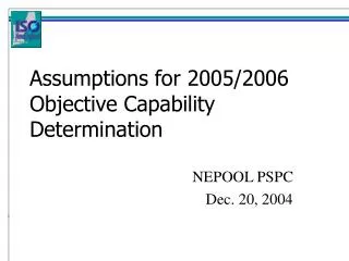
Third NSF Workshop on US-Africa Research and Education Collaboration Abuja, Nigeria, December 13-15, 2004 Available Transfer Capability Determination Chen-Ching Liu and Guang Li University of Washington
Overview • Background of Available Transfer Capability (ATC) • Definitions of ATC • Determination of ATC • Examples of ATC in Nigerian NEPA 330kV Grid • Optimization Technique to Calculate ATC • Stability-Constrained ATC Calculation Method • Conclusions Third US-Africa Research and Education Collaboration Workshop Abuja, Nigeria, December 13-15, 2004
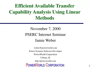
Background • ATC is the transmission limit for reserving and scheduling energy transactions in competitive electricity markets. • Accurate evaluation of ATC is essential to maximize utilization of existing transmission grids while maintaining system security. Third US-Africa Research and Education Collaboration Workshop Abuja, Nigeria, December 13-15, 2004
Transmission Service Types • Recallable transmission service: Transmission service that a transmission provider can interrupt in whole or in part. • Non-recallable transmission service: Transmission service that cannot be interrupted by a provider for economic reasons, but that can be curtailed for reliability. Third US-Africa Research and Education Collaboration Workshop Abuja, Nigeria, December 13-15, 2004
Power Flow A to B (MW) Stability Limit Voltage Limit Thermal Limit Total Transfer Capability Time ATC Under Operating Constraints • Transfer capability must be evaluated based on the most limiting factor. Third US-Africa Research and Education Collaboration Workshop Abuja, Nigeria, December 13-15, 2004
MW Total Transfer Capability (TTC) A->B TRM Transmission Reliability Margin Nonrecallable TRM ATC Recallable ATC Recallable Nonrecallable ATC Available Transfer Recallable Capability Recallable Scheduled Reserved Nonrecallable Reserved Nonrecallable Nonrecallable Reserved Scheduled Time Operating Horizon Planning Horizon Available Transfer Capability (ATC) (North American Electric Reliability Council) Third US-Africa Research and Education Collaboration Workshop Abuja, Nigeria, December 13-15, 2004
Definition of ATC • ATC = TTC – TRM – Existing Transmission Commitments (including CBM) • Transmission Transfer Capability Margins • Transmission Reliability Margin (TRM) • Capacity Benefit Margin (CBM) Third US-Africa Research and Education Collaboration Workshop Abuja, Nigeria, December 13-15, 2004
Transmission Reliability Margin (TRM) • Uncertainty exists in future system topology, load demand and power transactions • TRM is kind of a safety margin to ensure reliable system operation as system conditions change. • TRM could be 8% or 10% of the TTC Third US-Africa Research and Education Collaboration Workshop Abuja, Nigeria, December 13-15, 2004
Capacity Benefit Margin (CBM) • CBM is reserved by load serving entities to ensure access to generation from interconnected systems to meet generation reliability requirements. • Intended only for the time of emergency generation deficiencies Third US-Africa Research and Education Collaboration Workshop Abuja, Nigeria, December 13-15, 2004
ATC Methods Description DC Power Flow Model, Thermal Limit Only Linear Approximation Method AC Power Flow Model, Thermal Limit + Voltage Limit (Voltage Collapse) Continuation Power Flow Method AC Power Flow Model, Thermal Limit + Voltage Limit Optimal Power Flow Method Time Domain Simulations with Dynamic Model Stability-Constrained ATC Method State of the Art: ATC Methods Third US-Africa Research and Education Collaboration Workshop Abuja, Nigeria, December 13-15, 2004
First Contingency Incremental Transfer Capability (FCITC) & First Contingency Total Transfer Capability (FCTTC) FCITC FCTTC BASE POWER TRANSFERS Third US-Africa Research and Education Collaboration Workshop Abuja, Nigeria, December 13-15, 2004
Total Transfer Capability (TTC) • System Conditions • Critical Contingencies • Parallel Path Flows • Non-Simultaneous and Simultaneous Transfers • System Limits Third US-Africa Research and Education Collaboration Workshop Abuja, Nigeria, December 13-15, 2004
Procedure to Calculate TTC • Start with a base case power flow • Increase generation in area A and increase demand in area B by the same amount • Check the thermal, stability and voltage constraints. • Evaluate the first contingency event and ensure that the emergency operating limits are met. • When the emergency limit is reached for a first contingency, the corresponding (pre-contingency) transfer amount from area A to area B is the TTC. Third US-Africa Research and Education Collaboration Workshop Abuja, Nigeria, December 13-15, 2004
Example 1: 2-Area NEPA 330kV Grid Third US-Africa Research and Education Collaboration Workshop Abuja, Nigeria, December 13-15, 2004
2-Area Base-Case Tie Flow Single transmission line contingency Notation No thermal limit (assumed 120% base case flow) reached First thermal limit reached 4.64 MW Tie Line Flow 21 23 Area 1 Area 2 Third US-Africa Research and Education Collaboration Workshop Abuja, Nigeria, December 13-15, 2004
Area 1 to Area 2 ATC Calculation > 4.64 MW Increasing Generation DP MW Increasing Demand DP MW 21 23 Area 1 Area 2 Increased Demand 0.32 MW Increased Generation 0.32 MW 4.96 MW 7-25 21 23 2-8 FCTTC Area 1 Area 2 FCITC Third US-Africa Research and Education Collaboration Workshop Abuja, Nigeria, December 13-15, 2004
Area 2 to Area 1 ATC Calculation < 4.64 MW Increasing Demand DP MW Increasing Generation DP MW 21 23 Area 1 Area 2 Increased Generation 0.1 MW Increased Demand 0.1 MW 4.54 MW 21 23 5-24 7-25 FCTTC Area 1 Area 2 FCITC Third US-Africa Research and Education Collaboration Workshop Abuja, Nigeria, December 13-15, 2004
2-Area ATC Calculation Third US-Africa Research and Education Collaboration Workshop Abuja, Nigeria, December 13-15, 2004
Example 2: 4-Area NEPA 300kV Grid AREA 1 AREA 3 AREA 2 AREA 4 Third US-Africa Research and Education Collaboration Workshop Abuja, Nigeria, December 13-15, 2004
4-Area Base-Case Tie Flows Area 1 8.5 MW 8.24 MW 16.6 MW 4.64 MW Area 4 Area 3 Area 2 Third US-Africa Research and Education Collaboration Workshop Abuja, Nigeria, December 13-15, 2004
Area 3 to Area 1 ATC calculation (Example of Parallel Path Flows) Area 1 FCTTC = 9.1+ 8.65 = 17.75 MW FCITC = 17.75 (8.5 + 8.24) = 1.01 MW Increased Demand 1.01 MW 9.1 MW 8.65 MW 17.2 MW 4.64 MW 1-7 7-25 Increased Generation 1.01 MW Area 4 Area 3 Area 2 Third US-Africa Research and Education Collaboration Workshop Abuja, Nigeria, December 13-15, 2004
Area 4 to Area 2 Simultaneous ATC with a Pre-existing Area 3 to Area 1 17.75 MW Transfer Area 1 FCTTC = 16.99 (17.2)= 0.21 MW FCITC = 4.85 4.64 = 0.21 MW 9.1 MW 8.65 MW Increased Generation 0.21 MW 16.99 MW 4.85 MW 4-10 Increased Demand 0.21 MW 7-25 Area 4 Area 3 Area 2 Third US-Africa Research and Education Collaboration Workshop Abuja, Nigeria, December 13-15, 2004
Optimization Technique to Calculate ATC sum of generation in sending area A Objective: - system dynamic behavior - power flow equations Subject to - active power output - thermal limit - voltage profile - energy margin Third US-Africa Research and Education Collaboration Workshop Abuja, Nigeria, December 13-15, 2004
Time Domain Simulation (ETMSP) System trajectory Second-Kick based Energy Margin Computation Yes (EM = 0) ? ATC No Energy Margin Sensitivity Analysis with BFGS Method Generation Adjustment Stability-Constrained ATC Third US-Africa Research and Education Collaboration Workshop Abuja, Nigeria, December 13-15, 2004
Second-kick-based energy margin computation Perform time-domain simulation - Simulation Obtain system trajectory following a pre-specified disturbance sequence - Trajectory Compute potential energy of first- and second-kick trajectories - Potential energy Potential energy difference at the respective peaks of the first- and second-kick disturbances - Energy margin Third US-Africa Research and Education Collaboration Workshop Abuja, Nigeria, December 13-15, 2004
Energy margin sensitivity computation • Determine the search direction with the Broyden-Fletcher-Goldfarb-Shanno (BFGS) method D is an approximation to the inverse of Hessian matrix Third US-Africa Research and Education Collaboration Workshop Abuja, Nigeria, December 13-15, 2004
Generation adjustment - Adjustment - Update Third US-Africa Research and Education Collaboration Workshop Abuja, Nigeria, December 13-15, 2004
Net power transferred from area A to area B in the base case = 453 MW Area B Area A 453 MW 2-Area Test System Third US-Africa Research and Education Collaboration Workshop Abuja, Nigeria, December 13-15, 2004
Stability-Constrained ATC Results Third US-Africa Research and Education Collaboration Workshop Abuja, Nigeria, December 13-15, 2004
Conclusions • ATC provides a reasonable and dependable indication of available transfer capabilities in electric power markets. • ATC considers reasonable uncertainties in system conditions and provides operating flexibility for the secure operation of the interconnected network. • The effects of simultaneous transfers and parallel path flows are studied. • Need for ATC calculation method to incorporate voltage, angle stability limits as well as thermal limits. Third US-Africa Research and Education Collaboration Workshop Abuja, Nigeria, December 13-15, 2004
References [1] North American Electric Reliability Council, “Available Transfer Capability Definitions and Determination”, June 1996. [2] North American Electric Reliability Council,“Transmission Transfer Capability”, May 1995. [3] S. K. Joo, C. C. Liu, Y. Shen, Z. Zabinsky and J. Lawarree, “Optimization Techniques for Available Transfer Capability (ATC) and Market Calculations,” IMA Journal of Management Mathematics (2004) 15, 321-337. Third US-Africa Research and Education Collaboration Workshop Abuja, Nigeria, December 13-15, 2004