Download
1 / 41
560 likes | 1.58k Views
TRAFFIC AND OVERLOAD CONTROL IN TELEPHONE NETWORKS. Dynamic aspects of multiplexing the information flows from various users into a single high-speed digital transmission line. Problem of concentration that involves the sharing of a number of trunks by a set of users.

E N D
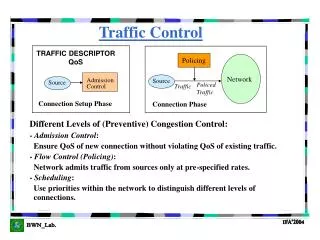
Dynamic aspects of multiplexing the information flows from various users into a single high-speed digital transmission line. • Problem of concentration that involves the sharing of a number of trunks by a set of users. • Problem of ensuring that there are sufficient resources, namely, trunks, to provide high availability, that is, low probability of blocking. We find that concentration can lead to very efficient usage of network resources if the volume of traffic is sufficiently large. • Routing methods in circuit-switching networks. Finally we consider approaches for dealing with overload conditions
1. Concentration • In Fig 4.43 numerous users at a given site, each with a communication line, need to use expensive trunks provided by a high-speed digital transmission line to connect to another location, for example, a telephone central office or another user site. • The number of trunks in use varies randomly over time but is typically much smaller than the total number of lines. • For this reason, a multiplexer is introduced to concentrate the requests for connections over a smaller number of trunks. The objective is to maximize the use of the trunks, typically a maximum acceptable probability of blocking is specified. ie connection request is blocked when no trunks are available.
Thus the system design problem involves selecting the number of trunks so that the blocking probability is kept below the specified level. • Fig 4.44 shows the occupancy of a set of seven trunks over time. The shaded rectangles indicate periods when a given trunk is in use. The upper part of the figure shows the corresponding N( t) , the number of trunks in use at time ‘t’ . In this example the system is in a blocking state when N (t) = 7. • The users require trunk connections in a sporadic and unscheduled manner. Nevertheless, the statistical behavior of the users can be characterized. In particular it has been found that user requests for connections take place according to a Poisson process with connection request rate λ calls/second. A Poisson process is characterized by the following two properties:
The time that a user maintains a connection is called the holding time. In general, the holding time X is a random variable. The average holding time E ( X) can be viewed as the amount of ``work'' that the transmission system has to do for a typical user. • In telephone systems typical conversations have a mean holding time of several minutes. The offered load a is defined as the total rate at which work is offered by the community of users to the multiplexing system:
Fig 4.45 shows the blocking probability for various offered loads as the number of trunks c is increased. As expected, the blocking probability decreases with the number of trunks. A 1% blocking probability is typical in the design of trunk systems. Thus from the fig it is seen that four trunks are required to achieve this Pb requirement when the offered load is one Erlang. • On the other hand, only 16 trunks are required for an offered load of nine Erlangs. This result shows that the system becomes more efficient as the size of the system increases, in terms of offered load. • The efficiency can be measured by trunk utilization that is defined as the average number of trunks in use divided by the total number of trunks. The utilization is given by
Table 4.2 shows the trunk utilization for the various offered loads and Pb = 0:01. Note that for small loads the utilization is relatively low. • In this case extra trunks are required to deal with surges in connection requests. However, the utilization increases as the size of the systems increases in terms • of offered load. For a load of two Erlangs, a total of 7 trunks is required; however, if the load is tripled to six Erlangs, the number of trunks required, 13, is less than double. The entry in Table 4.2 for offered loads of 50 and 100 Erlangs shows that high utilization is possible when the offered loads are large. • These examples demonstrate how the sharing of network resources becomes more efficient as the scale or size of the system increases. • The improvement in system performance that results from aggregating traffic flow is called multiplexing again.
Routing Control • Routing control refers to the procedures for assigning paths in a network to connections. Clearly, connections should follow the most direct route, since this approach uses the fewest network resources. • However, it is seen that when traffic flows are not large the required set of resources to provide high availability, that is, a blocking probability of 1%, will be used inefficiently. • Economic considerations lead to an approach that provides direct trunks between switches that have large traffic flows between them and that provide indirect paths through tandem switches for smaller flows. • A hierarchical approach to routing is desirable when the volume of traffic between switches is small. This approach entails aggregating traffic flows onto paths that are shared by multiple switches.
Consider the situation in Fig 4.46 where switches A, B, and C have 10 Erlangs of traffic to D, E, and F. • Suppose that switches A, B, and C are close to each other and that they have access to tandem switch 1. Similarly, suppose that switches D, E, and F are close to each other and have access to tandem switch 2. Furthermore, suppose that the distances between switches A, B, and C and D, E, and F are large. • From Table 4.2,each pair of switches requires 18 long distance trunks to handle the 10 Erlangs of traffic at 1% blocking probability. Thus the approach in Fig4.46a requires 9 x 18 = 162 trunks. • Concentrating the traffic flows through the tandems reduces to 106 the number of trunks required to handle the combined 90 Erlangs of traffic. • The second approach does require the use of local trunks to the tandem switch, and so the choice depends on the relative costs of local and long-distance trunks.
The increase in efficiency of trunk utilization that results from the increased offered load introduces a sensitivity problem. The higher efficiency implies that a smaller number of spare circuits is required to meet the 1% blocking probability. • However, the smaller number of spare circuits makes the system more sensitive to traffic overload conditions. For example, if each trunk group in part (a) is subjected to an overload of 10% the resulting offered load of 11 Erlangs on the 17 trunks results in an increased blocking probability of 2.45%. On the other hand, the 10% overload on the trunk group in part (b) results in an offered load of 99 Erlangs to 106 trunks. • The blocking probability of the system increases dramatically to 9.5%. In other words, the blocking probability for large systems is quite sensitive to traffic overloads, and therefore the selection of the trunk groups must provide a margin for some percentage of overload.
Fig 4.47 shows a typical approach for routing connections between two switches that have a significant volume of traffic between them. A set of trunks is provided to directly connect these two switches. A request for a connection between the two switches first attempts to engage in a trunk in the direct path. • If no trunk is available in the direct path, then an attempt is made to secure an alternative path through the tandem switch. The number of trunks in the direct route is selected to have a high usage and hence a blocking probability higher than 1% say, 10%.
The number of trunks available in the alternative route needs to be selected so that the overall blocking probability is 1%. Note that because only 10% of the traffic between the switches attempts the alternative route, a 10% blocking probability on the alternative path is sufficient to bring the overall blocking probability to 1%. • It should be noted also that the Erlang formula • cannot be applied directly in the calculation of blocking probability on the alternative route. The reason is that the requests for routes to the tandem switch arrive only during periods when the high-usage route is unavailable.
Fig 4.48 shows a more realistic scenario where the tandem switch handles overflow traffic from some high-usage trunk groups and direct traffic between switches that have small volumes of traffic between them. • Note that in this case the traffic between switches A and D must be provided with a 1% blocking probability, while a 10% blocking probability is sufficient for the other pairs of switches. • To achieve this blocking probability the traffic from A to D must receive a certain degree of preferential access to the trunks between the tandem switches. • Traffic flows vary according to the time of day, the day of the week, and even the time of year.
The ability to determine the state of network links and switches provides an opportunity to assign routes in more dynamic fashion. • For example, time/day differences between the East Coast and the West Coast in North America allow the network resources at one coast to provide alternative routes for traffic on the other coast during certain times of the day. Dynamic nonhierarchical routing (DNHR) is an example of this type of dynamic approach to routing calls. • As shown in Fig4.49, the first route attempt between two switches consists of a direct route. A certain number of tandem switches is capable of providing a two-hop alternative route. The order in which tandem switches are attempted as alternative routes is determined dynamically according to the state of the network. • The AT&T long-distance network consists of approximately 100 switches almost interconnected entirely with direct links.
Overload Controls • Traffic and routing control are concerned with the handling of traffic flows • during normal predictable network conditions. Overload control addresses the • handling of traffic flows during unexpected or unusual conditions, such as occur during holidays (Christmas, New Year's Day, and Mother's Day), catastrophes(e.g., earthquakes), or equipment failures (e.g., a fire in a key switch or a cut in a • key large-capacity optical fiber).
Overload conditions result in traffic levels that the network equipment has not been provisioned for and if not handled properly can result in a degradation in the level of service offered to all network customers. • The situation can be visualized as shown in Fig 4.50. Under normal conditions the traffic carried by the network increases or decreases with the traffic that is offered to it. As the offered traffic approaches network capacity, the carried traffic may begin to fall. • The reason for this situation is that as network resources become scarce, many call attempts manage to seize only some of the resources they need and ultimately end up uncompleted.
One purpose of overload control is to ensure that a maximum number of calls are completed so that the carried load can approach the network capacity under overload conditions. • Network monitoring is required to identify overload conditions. Clearly the traffic loads at various links and switches need to be measured and tracked. • In addition, the success ratio of call attempts to a given destination also needs to be monitored. The answer/bid ratio measures this parameter. • The traffic load measurement in combination with the answer/bid ratio is useful in diagnosing fault conditions. For example, the failure of switch A will result in an increased traffic level at other switches due to reattempts from callers to switch A.
The increased traffic load indicates a problem condition but is not sufficient to identify the problem. The answer/bid ratio provides the information that identifies switch A as the location of the problem. • Network monitoring software is used to process alarms that are set by the monitoring system to diagnose problems in the network. Once an overload condition has been identified, several types of actions can be taken, depending on the nature of the problem. One type of overload control addresses problems by allocating additional resources.
Many transmission systems include backup redundant capacity that can be activated in response to failures. For example, SONET transmission systems use a ring topology of add-drop multiplexers to provide two paths b/w any two stations on the ring. • Additional redundancy can be provided by interconnecting SONET rings using DCCs. Dynamic alternative routing provides another approach for allocating resources between areas experiencing high levels of traffic. • Certain overload conditions cannot be addressed by allocation of additional resources.
The overload controls in this case act to maximize the efficiency with which the available resources are utilized. For example, in the case of network wide congestion the routing procedures could be modified so that all call attempts, if accepted, are met using direct routes. Alternative routes are disallowed because they require more resources to complete calls. • As a result, the traffic carried by the network is maximized.
CELLULAR TELEPHONE NETWORKS • Cellular telephone networks extend the basic telephone service to mobile users with portable telephones. Unlike conventional telephone service where the call to a telephone number is directed to a specific line that is connected to a specific switch, in cellular telephony the telephone number specifies a specific subscriber‘s mobile station (telephone). Much of the complexity in cellular telephony results from the need to track the location of the mobile station.
SATELLITE CELLULAR NETWORKS • Satellite-based networks using the cellular concept are being deployed to provide global communications. In these systems the entire planet is covered by a constellation of satellites that allow communications from one point in the world to another. • These systems can be designed to provide true global personal communications where users with a mobile terminal communicate with the nearest satellite in the constellation and from there to other users anywhere in the world. • These systems can also be designed to provide a broadband network in the sky.
The period of time T that it takes a satellite to rotate around the earth is given by the equation
where A is the earth's radius (6378 km) plus the altitude of the satellite, and the gravitational constant is g = 3:99 x 105km3/s2 • Traditional geostationary earth orbit satellites (GEOS) are placed in an orbit approximately 35,786 km above the earth's surface at the equator. • The rotation of the satellite is then synchronized to that of the earth, so the satellite appears stationary with respect to the earth. At this altitude, the spatial beam of a GEO satellite can cover a large part of the word, and earth station antennas do not need to track the satellite because it is stationary. However, the high altitude implies a round-trip transmission timeto the satellite of approximately 270 ms.
In satellites two separate frequency bands are used for communications in the uplink and downlink direction to minimize interference between the transmitter and receiver. In early satellites the frequency band available was divided into multiple channels using frequency-division multiplexing. • At the satellite each channel in the uplink would be translated to a different frequency prior to being broadcast in the downlink. Later time-division multiplexing was used to share the access to the transmission medium.