Download
1 / 7
70 likes | 100 Views
Explore free-body diagrams of various mechanical systems, including beams, pulleys, and blocks, to understand forces and tensions in equilibrium. Engage with interactive examples for comprehensive learning.

E N D
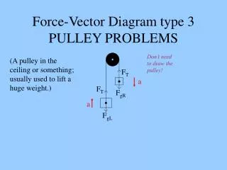
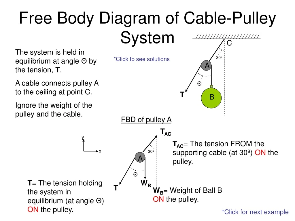
Free Body Diagram of Cable-Pulley System TAC y TAC= The tension FROM the supporting cable (at 30º) ON the pulley. x 30º Θ T= The tension holding the system in equilibrium (at angle Θ) ON the pulley. WB T WB= Weight of Ball B ON the pulley. *Click for next example C The system is held in equilibrium at angle Θ by the tension, T. A cable connects pulley A to the ceiling at point C. Ignore the weight of the pulley and the cable. 30º *Click to see solutions A Θ T B FBD of pulley A A
Free Body Diagram of Suspended Man R1 R1= Reaction force FROM rope ON man T1 y T1= Tension FROM rope ON man x W W = Weight of man *Click for next example The man is sliding across the rope on a bar and being pulled by the tension T. Ignore any frictional effects. *Treat the man and bar as one object FBD of Man T1 *Click to see solutions
Free Body Diagram of Beam With Applied Moment and Force F = The applied force ON the beam. F RB = The reaction force FROM ground point B ON the beam RA = The reaction force FROM ground point A ON the beam M M = The applied moment on the beam. RA RB *Click for next example F The beam at rest has an applied moment, M, and an applied Force, F. It is resting on two I-beams at A and B. Ignore the weight of the beam. I I B A M *Click to see solutions FBD of Beam
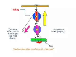
Free Body Diagram of Multiple Pulley-Cable System e c d a b F F B 1 2 A Block A is supported by the pulley system shown. The force, F, is pulling the rope downward. Ignore the weight of the pulleys. *Click to see solutions
Free Body Diagram of Multiple Pulley-Cable System Tc = Tension FROM cable ON pulley B. R1 = Reaction force ON block A FROM support 1. Td = Tension FROM cable ON pulley B. R2 = Reaction force ON block A FROM support 2. R2 = Reaction force FROM support 2 ON pulley B. W = Weight of block A. y Tc Td R1 R2 x W *Click for next example R2 e c d b a F F B 2 1 A *Click to see solutions Free body diagram of the block Free body diagram of the pulley at B A B
Free Body Diagram of Multiple-Spring System y x T1= Tension FROM spring 1 ON block A T1 T2 = Tension FROM spring 2 ON ball B T2 WB= Weight of block B T2 WA T2 = Tension FROM spring 2 ON block A WB WA = Weight of block A *Click for next example 1 The system is at rest. A 2 B *Click to see solutions FBD of Block A FBD of Ball B A B
Free Body Diagram of Beam Resting on Angled Surfaces F F = The applied force ON the beam. F The beam is resting on two smooth surfaces. There is an applied force, F, and a tension, T, on the rope. B A 30º 60º *Click to see solutions FBD of Beam T RB = The reaction force FROM ground point B ON the beam Original surface Original surface 30º 30º 60º 60º RA = The reaction force FROM ground point A ON the beam RB T RA W T = The tension force FROM the rope ON the beam. W = Weight of the beam *Click for next example