
Optimizing Patient Doses in Radiology: Best Practices and Techniques
E N D
Presentation Transcript
First FRCR Examination in Clinical RadiologyGeneral Radiation Protection(3h)John SaundersonRadiation Protection Adviser
Radiation protection of the patient • Justification - • Optimisation - • Limitation - X
Ways to Optimising Patient Doses in Radiology • minimise exposure time • minimise radiation field size • maximise tube voltage (kV) • maximise beam filtration • maximise tube to patient distance (FSD) • minimise pulses per second • minimise acquisition images • minimise use of CT • have a good quality assurance programme
OPTIMISATIONField Size • Don’t irradiate more tissue than necessary • Larger fields = • larger doses to patient • larger doses to staff (from scattered radiation) • more scatter, resulting in more blurred images Some examples of poorly collimated paediatric chest radiographs
OPTIMISATIONExposure Time • Don’t use X-rays at all if other non-radiation techniques can reasonably be used • Don’t irradiate for longer than necessary • If you are not looking at the monitor stop screening • Use the freeze frame facility whenever appropriate
OPTIMISATIONX-Ray Tube Voltage (kV) (more detail in lecture 4) On some sets kV can be selected by the operator. On fluoroscopy sets it is normally selected automatically, but different user selectable settings will affect how the automatic kV works. Higher kV radiation is more penetrating, so lower intensity beam into patient required to give same intensity out of patient to imager
From NIST Physical Reference Data (http://physics.nist.gov/PhysRefData/XrayMassCoef/cover.html)
Photoelectric Absorption • m x Z3 / E3 • = linear attenuation coefficient for PE effect • m = mass density (kg/m3) • Z = atomic number • E = photon energy
Compton Scattering • m x e / E • = linear attenuation coefficient for PE effect • m = mass density (kg/m3) • e = electron density (e- per kg) [Z/A] • E = photon energy
Comparing 1/E3 to 1/E(Photoelectic effect to Compton scattering energy response))
From NIST Physical Reference Data (http://physics.nist.gov/PhysRefData/XrayMassCoef/cover.html)
OPTIMISATIONX-Ray Tube Voltage (kV) (continued) Higher kV radiation is more penetrating, so lower intensity beam into patient required to give same intensity out of patient to imager Therefore, higher kV = lower patient dose e.g. changing up from 90 to 110 kV may lead to a 26% reduction in skin dose changing down from 90 to 70 kV may lead to a 62 % increase in skin dose So at lower kV values the threshold for erythema can be reached in a shorter screening time On some sets “low dose mode” forces the X-ray set to use higher kV settings, and “high contrast mode” forces it to use lower kV settings.
OPTIMISATIONX-Ray Tube Voltage (kV) (continued) • Example – a 1 mm wire in the trunk, comparing 90kV to 110kV beam • Skin dose 26% lower for 110 kV • Effective dose 10% lower for 110 kV • Contrast 15% higher for 90 kV But, because a higher kV beam is more penetrating then it will also less contrast between different materials Therefore, higher kV = less contrast You must have sufficient contrast to see what you need to in order to perform the clinical procedure, but a higher than necessary contrast can result in a higher risk of patient skin reactions, a higher risk of cancer induction in patients and staff, and a higher risk of exceeding your eye or other dose limit which could prevent you working with X-rays until the following year.
OPTIMISATIONBeam filtration (more detail in lecture 4) All X-ray sets must have a metal filter (typically around 2 mm of aluminium) to remove very low energy X-rays which would never penetrate the patient and reach the imager, but would significantly increase the dose to the patient. Most modern fluoroscopy sets also have removable copper filters of a few tenths of a millimetre built into the X-ray tube housing. On some fluoroscopy sets the added copper filtration can be selected by the operator. On others it is normally selected automatically, but different user selectable settings will affect how much filtration is automatically driven into the beam.
OPTIMISATIONBeam filtration (continued) On some sets “low dose mode” forces the X-ray set to use extra copper filters, and “high contrast mode” forces it to use no copper filter. • Example – a 1 mm wire in the trunk in a 90kV beam, • comparing no copper filter with using a 0.1 mm copper filter • Skin dose 29% lower with 0.1 mm copper filter • Effective dose 4.3% lower with 0.1 mm copper filter • Contrast is 4.5% higher for no copper More filtration effectively means the average energy of the X-rays is higher, and so with more filtration the beam is more penetrating. In exactly the same way as higher kV beams give lower patient skin dose but also lower contrast, more filtration will do exactly the same. Use the maximum filtration you can while still maintaining adequate image quality for the task you are undertaking.
Transmission through 10 cm tissue • 80 keV 16 % • 60 keV 13 % • 50 keV 10 % • 40 keV 7 % • 30 keV 2 % • 20 keV 0.04 % • 15 keV 0.000008 % • 10 keV 10-21 %
Minimum Filtration • General tube 2.5 mm aluminium • Mammography 0.03 mm molybdenum or 0.5 mm Al • Dental ( 70kVp) 1.5 mm Al • Dental (> 70kVp) 2.5 mm Al
Tube to Patient Distance Greater FSD = lower patient dose e.g. from 50 to 70 cm 49% skin dose Greater FSD = less magnification (so fewer distortions) Tube to patient distance never < 30cm, preferably > 45cm for chests > 60 cm.
Tube to Patient Distance In fluoroscopy always have the patient as close to the imager as possible as far from X-ray tube as possible Greater FSD# = lower patient dose e.g. from 50 to 70 cm FSD 49% skin dose Greater FSD = less magnification (so fewer distortions) (# FSD = focus to skin distance, where the focus is the source of the X-rays inside the X-ray tube)
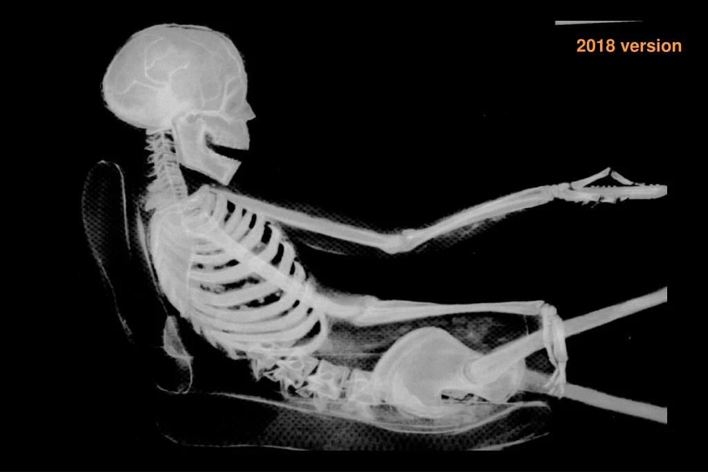
One of the main causes of unnecessary radiation injury to patients is bad positioning, with the patient (or part of the patient such as their arm) too close to the X-ray tube Approximate screening times to reach erythema threshold dose(At 20 – 100 mGy/min, 70 cm FSD) • 70 cm from focus = 20 - 100 mins • 50 cm from focus = 10 -50 mins • 30 cm from focus = 3 - 18 mins
Fluoroscopy • Only expose when looking at monitor • Keep patient close to image intensifier and far from tube (at least 30 cm from tube for mobile, 45 cm for static) • Use low dose setting, unless image unacceptable (i.e. high kV, high filtration) • Magnification increases dose rate to skin (although a smaller area irradiated) • Cone down where practicable • Special care if skin dose likely to exceed 1 Gy.
Skin dose rate (mGy/min) HRI IRT3 with 18.5 cm Perspex phantom Remedial level: 50 mGy/min for largest field (standard patient) Suspension level: 100 mGy/min (standard patient)
Frame rate / Pulses per second • Fewer pulses per second = less dose • e.g. 15 pps gives half the dose of 30 pps • Fewer pulses per second = potential blurring if there is patient/organ movement Use the lowest frame rate you can while still maintaining adequate image quality for the task you are undertaking.
Fluoroscopy Dose Modes • “Low dose” • higher kV (lower mA) • more copper filtration • therefore, lower contrast • “High contrast” • lower kV (higher mA), • less copper filtration • therefore higher dose
Screening and Acquisition • Screening uses a low dose rate, allowing movement to be observed. • Acquisition/spot images use a higher radiation dose for a short time to reduce noise in the image and take a high quality snapshot. • Only use acquisition when you really need the extra image quality, and then use sparingly.
Screening dose vs Acquisition dosee.g. HRI CP1, 20 cm field size, 18.5 cm Perspex phantom • Screening • 77 kV, 2.2 mA • Skin dose rate 19 mGy/min • (Erythema threshold 105 min) • Digital acquisition • 80 kV, 475 mA, 32 ms • Skin dose 2.5 mGy/image • (Erythema threshold 800 images) • So in this example, in terms of patient skin dose • 1 spot image 8 seconds of screening
General Good Practice in Fluoroscopy • Only expose when looking at monitor (if you are not then the radiation dose to the patient and staff has no benefit) • Keep patient close to image intensifier and far from tube (at least 30 cm from tube for mobile, 45 cm for static) • Use low dose setting, unless image unacceptable • Magnification increases dose rate to skin (although a smaller area irradiated, effectively more dose is squeezed into a smaller area to get a bright enough image) • Cone down where practicable • Take special care if skin dose is likely to exceed 1 Gy, as erythema may be caused#. Note, higher patient dose also means higher dose to you and other staff in the X-ray room (# some sets display “skin dose”, but this assumes an average size patient in a standard set up. So “1 Gy” displayed could be above the 2 Gy erythema threshold for a real patient.)
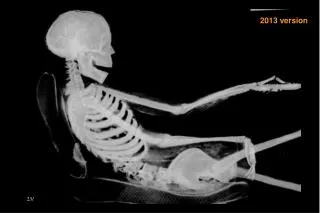
Computed Tomography (CT) • (Covered in more detail in Craig Moore’s lectures) • High dose, so justification important • Lowest mA practicable • Minimum number of slices necessary • Angulation of gantry can substantially reduce eye dose. .
Individual procedure doses (UK averages) Conventional radiography CT Fluoroscopy HPA-CRCE-012 - http://webarchive.nationalarchives.gov.uk/20140629102627/http://www.hpa.org.uk/webc/HPAwebFile/HPAweb_C/1287148001641
Computed Tomography (CT) • (Covered in more detail in Craig Moore’s lectures) • High dose, so justification important • Optimise protocols (e.g. lowest mA practicable) • Minimum number of slices necessary • Angulation of gantry can substantially reduce eye dose. .
Dose quantities in CT • Computed Tomography Dose Index (CTDI, in Gy) • Average dose inside the beam
Weighted CTDI100 • CTDIw = 1/3CTDI100(centre) + 2/3CTDI100(peripheral)