System Design
System Design. Project Management Unit, Lecture 3. What is system design?. High level design identifying the system processes, functional components and their interfaces Derived from system requirements Provides an overview of the project Define the components that are needed

System Design
E N D
Presentation Transcript
System Design Project Management Unit, Lecture 3 System Design
What is system design? • High level design identifying the system processes, functional components and their interfaces • Derived from system requirements • Provides an overview of the project • Define the components that are needed • Establish how components “communicate” with other components • Determine how to modularize the project into discrete work packages • Identify critical interfaces that must be well defined • Used to provide initial cost, schedule & resource estimates • Usually little or few implementation details • As system design is refined, and lower level subsystems are included, implementation issues may need to be addressed System Design
System design steps • Define project goal and objectives • Develop the project system requirements • Identify the major system components that satisfy the system requirements • Identify the major system interfaces • Refine the system design • Define subsystems making up each component • Specify interfaces between subsystems • Establish management controls for the system interfaces System Design
Project goal and objectives • The goal specifies the overall purpose of the project • Defines what one wishes to accomplish as a result of the project • Objectives are discrete intended accomplishments during and resulting from the project • Science objectives describe the specific scientific results expected from the project • Technical objectives describe the specific technical accomplishments expected during the project • Together the project goal and objectives define and constrain the project scope • Leads to defining the system requirements System Design
System requirements • A document listing the constraints imposed upon and the results necessary from the project • The project goal as well as the scientific and technical objectives should be reflected in the system requirements • Time spent on detailing the system requirements is worthwhile • A greater understanding of what is required facilitates design and implementation and improves the chances of success • Initially focus on developing the high level scientific and technical requirements • Based upon current science knowledge, what is to be measured with what resolution and accuracy? • What constraints impose what technical limitations on your design? System Design
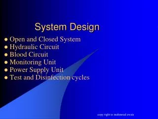
Initial System Design • Development of the initial system design can, at times, go hand-in-hand with refinement of the system requirements • Functions needed to satisfy the science requirements define the initial system • For example, to perform any science measurement • You will need a sensor (detector system) • You will need to power the sensor (power system) • You will need to read data from the sensor (data acquisition system) • You will need to store the data (data archive system) • You will need to control the sensor, readout, storage (control system) • You will need to analyze the data (ground data system) • These functions will also need to have a set of requirements specified • For example, the power system will need to supply volts & milliamps to the sensor, data acquisition, archive and control systems System Design
Traceability Matrix • Shows the relationship between requirements and the components that satisfy these requirements • Commonly used in software engineering, but has application to hardware as well • Used to assure that the system design properly addresses the project needs and does not incorporate any unnecessary components • Format of the matrix can vary widely but generally includes the following for each requirement • Identification number • Description of the requirement • Description of the component that satisfies the requirement • Description of test that verifies the components meets the requirement • One example is provided by the U.S. Department of Energy, Requirements Traceability Matrix Template System Design
Major System Interfaces • An interface describes the linkage between two functions or processes • Neglecting how your systems fit together can lead to disaster • NASA Mars Climate Orbiter failed in 1999 because ground systems used “English” units while the flight systems used “Metric” units! • There are multiple types of interfaces • Mechanical: How systems physically fit together • Power: What voltage and current flows between the systems • Electronic: The characteristics of electrical signals between systems • Data: Format and content of information transferred between systems • Thermal: How does heat flow between systems • Software: How modules communicate with other modules or hardware • The type and characteristics of all interfaces need to be identified and defined System Design
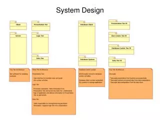
System Level Drawing Example • High level overview of a balloon platform that could carry eight student built payloads • Primary subsystems are identified • Directionality and content of major interfaces are identified System Design
Refining the System Design • After the major systems and interfaces are identified the subsystems are described • Each major function is composed of multiple activities, processes or modules each with a specific function of its own • For example, the Power System in the previous slide has the following subsystems • Power source that supplies the energy for the entire platform • Separate supplies to convert the source power to the proper volts and amps required by the FCU, DAU, DAU Disk, Aux XTM and Cubesats • Each of the subsystems has interfaces that need specification • How many of what kind of interface do the subsystems have? • Is the interface to another subsystem or another system? • What is the content of the interface? • Traceability matrix should include these new subsystems System Design
Subsystem Level Example • Subsystem design provides additional details • Major functional components are identified and expressed • Shows that system requirements are satisfied • Most important interface details are revealed • Still little hardware or implementation dependence System Design
Moving to Design Specifics • The system design refinement process continues by specifying the subsystems of the subsystems • For example, the FCU supply in the power system might include the following sub- subsystems • A relay to turn the supply on / off by computer control • A DC / DC converter to provide the required voltage from the source power • An inline sensor so that volts and amps can be monitored in real-time by the computer • With enough iterations the system design can evolve into an actual implementation • Actual components to use in the design start becoming apparent • Interfaces become very specific and well defined System Design
Refined Subsystem Example • Implementation and hardware details are starting to appear • Interfaces are close to being fully defined • Next step would be full hardware and interface specification System Design
Controlling Interfaces • Critical interfaces need to closely monitored by use of an Interface Control Document (ICD) • Written description of the interface that is modified only under specific, previously defined conditions and is used by team personnel for implementation • Not all interfaces need to be controlled, but an ICD can be helpful during system design • Written specification of the interface • Obtain agreement between stakeholders on the interface characteristics • Controlled ICDs should be used to help manage potential risks • When an interface error or mismatch could result in project failure • When stakeholders implementing the interface ends are separated in either geographic distance or time System Design
References • Managing Requirements Website, Ludwig Consulting Services, LLC, http://www.jiludwig.com/ • U.S. Department of Energy, Office of the Chief Information Officer, Systems Engineering / Project Management website http://cio.doe.gov/ITReform/sqse/project_management.htm • U.S. Department of Energy, Office of the Chief Information Officer, Systems Engineering Publications and Templates http://cio.doe.gov/ITReform/sqse/publications.htm System Design