Download
1 / 26
260 likes | 274 Views
SuperB Accelerator Overview and Status. P. Raimondi for the SuperB Accelerator Team Scientific Committee Rome May 21, 2008. Outline. SuperB project Luminosity and beam-beam Beam dynamics studies Conclusions. SuperB Project.

E N D
SuperB Accelerator Overview and Status P. Raimondi for the SuperB Accelerator Team Scientific Committee Rome May 21, 2008
Outline • SuperB project • Luminosity and beam-beam • Beam dynamics studies • Conclusions
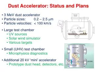
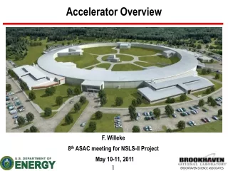
SuperB Project • SuperB aims at the construction of a very high luminosity (1-4 x 1036 cm-2 s−1 ) asymmetric e+e− Flavour Factory, with possible location at the campus of the University of Rome Tor Vergata, near the INFN Frascati National Laboratory.
SuperB Accelerator Contributors • M. E. Biagini, M. Boscolo, T. Demma, A. Drago, S. Guiducci, M. Preger, P. Raimondi, S. Tomassini, C. Vaccarezza, M. Zobov (INFN/LNF, Italy) • Y. Cai, A. Fisher, S. Heifets, A. Novokhatski, M.T. Pivi, J. Seeman, M. Sullivan, U. Wienands, W. Wittmer (SLAC, US) • T. Agoh, K. Ohmi, Y. Ohnishi (KEK, Japan) • I. Koop, S. Nikitin, E. Levichev, P. Piminov, D. Shatilov (BINP, Russia) • Wolski (Liverpool University, UK) • M. Venturini (LBNL, US) • S. Bettoni (CERN, Switzerland) • A. Variola (LAL/Orsay, France) • E. Paoloni, G. Marchiori (Pisa University, Italy)
SuperB Ring (about 1800m) SPARX SuperB Injector (about 400m) Roman Villa 100m SuperB Main Building SuperB footprint on Tor Vergata site
Beam-beam transparency conditions in red Super-B New Parameters
The SuperB Process (M. Biagini) 2th Joint Japan-US SuperB-Factory Workshop, Hawaii, US International SuperB Steering Committee established 4th SuperB Workshop, Villa Mondragone, Italy Accelerator test started at DAFNE, LNF, Italy International SuperB Study Group formed 5th SuperB Workshop in Paris, France International Review Committee setup CDR presented to INFN Management ICFA08 Workshop at BINP, Russia CERN strategy group presentation Detector R&D workshop, SLAC,US Physics retreat at Valencia, Spain 1st Accelerator retreat, SLAC, US 2th Accelerator retreat, SLAC, US 2nd SuperB Workshop, LNF, Italy 3rd SuperB Workshop, SLAC, US 1st SuperB Workshop, LNF, Italy SuperB meeting, Daresbury,UK 2nd IRC meeting, Rome, Italy SuperB Meeting in Elba, Italy Mini MAC, EPAC08, Italy 1st IRC meeting, LNF, Italy 2nd Meeting with ECFA CDR presented to ECFA CDR writing started CDR published • 9 11 3 4 6 9 11 12 • 5 5 7 7 9 11 12 1 2 3 44 6 6 .. Month 2005 2006 2007 2008
Basic concepts • B-Factories (PEP-II and KEKB) reached very high luminosity (>1034 s-1 cm-2 ), but to increase L of ~ two orders of magnitude bordeline parameters are needed, such as: • Very high currents • Smaller damping time Difficult and costly • Shorter bunches operation • Crab cavities for head-on collision • Higher power • SuperB exploits an alternative approach, with a new IP scheme: • Small beams (ILC-DR like) • Large Piwinski angle and “crab waist” • Currents comparable to present Factories
Crab-waist Studies at DAFNE at INFN Frascati • P. Raimondi et al: DAFNE upgrade with improved interaction region to focus tighter the beams at IP and have a “large” crossing angle large Piwinski angle • Features: • Smaller collision area • Lower b*y • No parasitic crossings • No synchro-betatron resonances due to the crossing angle • “Crab Waist” sextupoles • Results very encouraging so far with improved tunes shifts and higher luminosity with smaller currents.
IP beam distributions for KEKB • SuperB beams are focused in the y-plane100 times morethan in the present factories, thanks to: • - small emittances • - small beta functions • larger crossing angle • Tune shifts and longitudinal overlap are greatly reduced y(mm) x(mm) z(mm) IP beam distributions forSuperB y(mm) x(mm) z(mm)
Beams distribution at IP E. Paoloni Without Crab-sextupoles Crab sextupoles OFF waist line is orthogonal to the axis of one bunch Crab sextupoles ON With Crab-sextupoles waist moves to the axis of other beam All particles from both beams collide in the minimum by region, with a net luminosity gain
SuperB transparency condition • To have equal tune shifts with asymmetric energies in PEP-II and KEKB the “design” beam currents ratio is: I+/I-~ E-/E+ • Due to SuperB large crossing angle, new conditions are possible: LER and HER beams can have different emittances and b* and equal currents Present B-factories SuperB
Lmax = 2.2x1036 cm-2 s-1 Beam-beam Luminosity Tune Plane Scan (crab=0.8/q, sz = 7 mm; 3x10¹⁰ particles) 2D and 3D surface luminosity plots. The red color on the contour plot corresponds to the highest luminosity while the blue is the lowest. Each contour line corresponds to a 10% luminosity reduction. D. Shatilov, M. Zobov, IV SuperB Workshop
A. Novokhatski CDR parameters New parameters RF power estimate Including synchrotron radiation, HOMs and RF power with 50% klystron efficiency
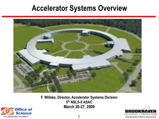
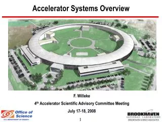
Lattice overview • The SuperB lattice as described in the Conceptual Design Report is the result of an international collaboration between experts from BINP, Cockcroft Institute, INFN, KEKB, LAL/Orsay, SLAC • Simulations were performed in many labs and with different codes: • LNF, BINP, KEK, LAL, CERN • The design is flexible but challenging and the synergy with the ILC Damping Rings which helped in focusing key issues, will be important for addressing some of the topics • Further studies after the CDR completion led to an evolution of the lattice to fit the Tor Vergata Site and to include polarization manipulation hardware.
HER LER Arc cells layout M. Biagini Cell #1 Cell #1 Cell #2 Cell #2
Crab sextupoles Final Focus optical functions (Öb) LER: bx* = 35 mm, by* = 220 m HER: bx* = 20 mm, by* = 390 m M. Biagini
HER spin manipulation hardware Full HER lattice Spin rotators in the HER Wittmer, Wienands, Biagini
Total length 1800 m 20 m 280 m Lattice layout, PEP-II magnets reuse Dipoles Available Needed Quads Sexts All PEP-II magnets are reused. Dimensions and fields are properly sized.
Polarization • Polarization of one beam is included in SuperB • Either energy beam could be the polarized one • The LER would be less expensive, the HER easier • HER was chosen for now. • Longitudinal polarization times and short beam lifetimes indicate a need to inject vertically polarized electrons. • The plan is to use a polarized e- source similar to the SLAC SLC source. • There are several possible IP spin rotators: • Solenoidslook better at present (vertical bends give unwanted vertical emittance growth) • Expected longitudinal polarization at the IP of about 87%(inj) x 97%(ring)=85%(effective) • Polarization section implementation in lattice: in progress with initial success
Example of spin rotators U. Wienands Proof-of-principle scheme No V-emittance growth. Maybe possible to incorporate into lattice using the Final Focus bends to provide the spin rotation. Work in progress
Accelerator & site cost estimate Note: site cost estimate not as detailed as other estimates.
Schedule • Overall schedule dominated by: • Site construction • PEP-II/BaBar disassembly, transport, and reassembly • The goal is to reach the commissioning phase after about 5 years from the start of the project.
Conclusions • The initial SuperB design meets the goals requested by the experimenters. • IR polarization rotators have now been added to the lattice. • Beam dynamics issues are receiving a fresh look. • The next phase for the accelerator group is to form a team to complete the Technical Design Report.