Download
1 / 13
140 likes | 329 Views
Variable Low Power FM Transmitter for use with Portable Audio Player. Communication Electronics – Dr. Pao-Lo Liu TA – Mr. Saurav Bandyopadhyay Jason Burgess Kee Soon Lim Terry Hudson. Objectives & Goals.

E N D
Variable Low Power FM Transmitter for use with Portable Audio Player Communication Electronics – Dr. Pao-Lo Liu TA – Mr. Saurav Bandyopadhyay Jason Burgess Kee Soon Lim Terry Hudson
Objectives & Goals • The device will function as a portable wireless FM transmitter with an input from the mini jack of a portable audio device. • The device will adhere to Title 47 of the Code of Federal Regulations (Part 15, subpart C), which states, “the power limit for unlicensed FM transmissions is a signal strength of 250 microvolts per meter, measured 3 meters from the transmitting antenna”
Design Specifications • Transmitter’s frequency range: 88-107Mhz • Effective Transmitter distance: 2-5 meters • Frequency Response: 10khz • Easily Portable • Variable Transmitted Frequency
Final Design Fig 1. The schematic of the final design.
Bread boarded Circuit The Pre-emphasis circuit The amplifier circuit The oscillator circuit Fig 2. Picture of the bread boarded circuit.
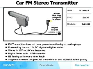
Operation and Analysis *The analysis was conducted with use of a Clarion DXZ735MP receiver, the specs are listed below. • FM frequency response 30-15kHz +0.0, -2.1 dB • SNR 74.4 dB mono, 71.2dB stereo • All measurements taken at 89.1 MHz carrier frequency.
Operation and Analysis Fig 3. Output at 100 Hz Fig 4. Output at 30 Hz
SNR • To measure the SNR an audio analysis file was acquired of a 1kHz sine wave. • The peak to peak voltage of a 1kHz sine wave was measured against the no signal noise level at different volumes of the input. Fig 5. SNR data SNR=20 log (Vs/Vn)
Effective Transmitter Distance • The same 1kHz sine wave was used as the input. • The output was measure by the receiver with three foot whip antenna attached. • A simple 18 in. long 20 gauge wire was used as the transmitter antenna. • The effective transmission distance was determined to be the straight line, antenna to antenna distance at which an attenuation of 3dB occurred. • The lab measurement was 6.4m (21 feet)
Frequency Response Figure 6- The output from the transmitter with the pre-emphasis. The –3 dB points are 85Hz, 14.5 kHz. The bandwidth is then 14kHz. Fig 6. Figure 7- The output from the transmitter with out the pre-emphasis. The –3 dB points are 80 Hz, 9.3 kHz. The bandwidth is then 9.2 kHz. Fig 7.
Possible Improvements • Soldering to a printed circuit board • Making use of a better antenna • Indicating transmission frequency on dial • Indicating transmission frequency using 7 segment LED displays.
Thank YouAny Questions? REFERENCES [1] http://sound.westhost.com/project54.htm [2] Electronic Communications Systems 5th ed., Tomasi, Wayne, Prentice Hall, 2003