Download
1 / 41
410 likes | 616 Views
5.1 REQUIREMENTS ANALYSIS. OVERVIEW/INTRODUCTION Requirements elicitation results in validated system specs with definition of boundary conditions and exceptional cases

E N D
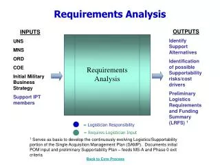
5.1 REQUIREMENTS ANALYSIS • OVERVIEW/INTRODUCTION • Requirements elicitation results in validated system specs with definition of boundary conditions and exceptional cases • OO analysis entails building an object model of the system, which extends the What’s and Why’s (of the elicitation) with the How’s of the system; as iterative as Elicitation • OO analysis results in defining the actor-object, object-object, and actor-object-actor interactions in the system’s application model • Together with the non-functional requirements, the developer develops the software architecture (model) of the system at System Design phase of the software process • System Analysis Phase Entails: • Object identification • Object behavior modeling • Object relationships • Object classification • Object organization or structuring • Formalizing activities avoids omissions and eliminates ambiguities • (See Fig 5-1)
5.2 REQUIREMENTS ANALYSIS • OVERVIEW AND FUNDAMENTALS • RA activities also focus on structuring and formalizing the elicited specs, allowing users and developers to abstractly make tough decisions about the system • (See Fig 5-2)
Requirements Elicitation system specification :Model Analysis analysis model :Model System Design system model :Model Figure 5-2. Products of requirements elicitation and analysis (UML activity diagram).
SYSTEMS ANALYSIS • OVERVIEW AND FUNDAMENTALS –2 • System analysis activities result in a correct, consistent, complete, verifiable analysis model – comprised of • Functional model: represented by scenarios and use cases • Analysis object model: represented by object and class diagrams • Dynamic model: represented as sequence diagrams and statecharts • (See Fig 5-3)
use case class statechart sequence diagram:View diagram:View diagram:View diagram:View functional object dynamic model:Model model:Model model:Model analysis model:Model Figure 5-3. The analysis model is composed of the functional model, the object model, and the dynamic model. In UML, the functional model is represented with use case diagrams, the object model with class diagrams, and the dynamic model with statechart and sequence diagrams.
SYSTEM ANALYSIS • 5.3 System Analysis Concepts • Entity objects: retain values or persistent info about the system (files, programs) • Boundary objects: objects that come between actors and the rest of the system or objects that directly interact with the actors (databases, OS, GUIs, I/O devices, controllers) • Control objects: comprise the rest of the system tasks that implement the user functions (read-file, compute, track-signal modules) • Having three object types • 1) allows distinction and offers simplicity (a basis leading to object identification) • 2) allows object specialization and categorization (leading to object structuring) • 3) fosters high cohesion (due to entity/control object placement) and low coherence (due to separation of boundary objects) • UML facilities for object modeling is via stereotyping and naming conventions • (See Fig 5-4)
<<entity>> <<control>> <<boundary>> Year ChangeDateControl ButtonBoundary <<entity>> <<boundary>> Month LCDDisplayBoundary <<entity>> Day Figure 5-4. Analysis classes for the 2Bwatch example.
SYSTEM ANALYSIS • System Analysis Concepts – 1 • Association multiplicity: labeling the end of an association, it indicates the number of links that can legitimately start from an object of the class (the source) connected to the end of the association (the target). The target label bears the number. The number at the start of the link (at the source) has the reverse semantics. • E.g., A 2Bwatch (source class: 1) with two Buttons (target class: 2) and one Display-unit (target class: 2) • (See Fig 5-5)
2Bwatch 1 1 2 1 Button LCDDisplay Figure 5-5. An example of multiplicity of associations (UML class diagram). A 2Bwatch has two Buttons and one LCDDisplay.
SYSTEM ANALYSIS • Association Multiplicity – 1 • An association multiplicity could be: • One-to-One: Student and Student-Number, Police-Officer and Police-Badge-Number • One-to-Many: (denoted 1:0..n or 1:*) implies composition – Fire-Unit, Fire-Trucks • Many-to-Many: (denoted *:* at both ends) - Authors and Books • Association multiplicities are useful in connecting instances of use case objects and specifying the required functionality (actions) of such objects • E.g., 1:* between Directory and FileSystemElement classes (strictly hierarchical) • or *:* between Directory and FileSystemElement classes (non-hierarchical) • Either model can impact the complexity of the ‘delete’ action described in the use cases • See Fig 5-7 Fig 5-8 (examples of ‘aggregation’)
* FileSystemElement 1 Directory File Figure 5-7. Example of a hierarchical file system. A Directory can contain any number of FileSystemElements (a FileSystemElement is either a File or a Directory). A given FileSystemElement, however, is part of exactly one Directory.
* FileSystemElement * Directory File Figure 5-8. Example of a nonhierarchical file system. A Directory can contain any number of FileSystemElements (a FileSystemElement is either a File or a Directory). A given FileSystemElement can be part of many Directory (ies).
SYSTEM ANALYSIS • Qualified Association • Allows simplification of the more complex 0:* or 1:* multiplicities • Using an attribute-name of a (target) class to qualify the (source) class name to simplify the multiplicity, e.g., a file_name attribute from a File class to qualify a DirectoryClass, effectively reducing a 1:* (on the many side) to association to 1:0..1 • (See Fig 5-9)
W ithout qualification File 1 * Directory filename W ith qualification 0..1 1 Directory File filename Figure 5-9. Example of how a qualified association reduces multiplicity (UML class diagram). Adding a qualifier clarifies the class diagram and increases the conveyed information. In this case, the model including the qualification denotes that the name of a file is unique within a directory.
SYSTEM ANALYSIS • Generalization • Generalization is for organizing concepts into hierarchies (with specialization and inheritance implications at the middle-to-bottom levels and generalized concepts at the top) (This is more suitable for modeling and analysis activities.) • Inheritance allows assumption of the properties (attributes, methods, environment) of the generalized or top class by the lower level class objects – offering a mechanism for reusability. (This is more semantic, semi-implementation level tool.) • (See Fig 5-10)
Incident LowPriority Emergency Disaster CatInTree EarthQuake ChemicalLeak TrafficAccident BuildingFire Figure 5-10. An example of a generalization hierarchy (UML class diagram). The root of the hierarchy represents the most general concept, whereas the leaves nodes represent the most specialized concepts.
SYSTEM ANALYSIS • 5.4 System Analysis Activities (That transform the scenarios/use cases to analysis model) • Identifying Entity Objects • Processing (manually or automatically or both) the natural language specs – use cases – from the requirements elicitation document by applying Abbot’s Heuristics to the use cases (This minimizes the drawbacks of ‘pure’ natural language processing of specs.) • Mappings: proper nouns -> objects (actors: Dispatcher, FieldOffcer) • common nouns -> classes (entity: EmergencyReport, Incident) • doing verbs -> operations • being verbs -> inheritance • having verbs -> aggregates • modal verbs -> constraints • adjectives -> attributes • Analyzing the ReportEmergency use case results in entity objects (Table 5-2) • Need tentative names, attributes, descriptions (no details), • See Fig 5.11 -- Applying Abbot’s method to the use case ReportEmergency, uncovers the Emergency-Report object in Table 5-2
SYSTEM ANALYSIS • Identifying Boundary Objects • Objects that come between the actors and the system (interfacing). I.e., each actor interacts with at least one boundary object • Boundary objects transform actor info into forms usable to entity and control objects, simply abstracting the ‘mechanism’ for the interfacing or transformation (e.g., a mouse, button, AcknowledgementNotice, DispatcherStation, IncidentForm, FieldOfficerStation, EmergencyReportForm) • Heuristics for extracting boundary objects • Identify the means (forms, manipulators) the actors need to interact with the system • Identify return data (feedbacks: acknowledgement, sound, screen-icons, codes) the system uses to respond to the actors • Focus on user terms to abstractly describe boundary objects • Analyzing Report Emergency use case results in boundary objects (Table 5-3) • Analyzing the use case uncovers the IncidentForm object related to the Dispatcher
SYSTEM ANALYSIS • Identifying Control Objects • Control objects are synonymous to ‘processes’ in, e.g., Unix OS – they are created at the start of use case definition, coordinate or perform tasks between boundary and entity objects, and fade away when the use case is exited • Control objects are used to model the control flow of the actors in use cases • E.g., ReportEmergencyControl (like a process) personified as the FieldOfficer (actor), represents the control object for creating the EmergencyReportForm for the officer, and after the form is filled in it creates an EmergencyReport and sends to the Dispatcher. This control object waits until the Dispatcher sends an acknowledgement, and then it creates an AcknowledgementNotice, and sends that to the FieldOfficerStation (boundary object) for eventual display on the officer’s workstation or laptop • (This control object’s counterpart is the ManageEmergencyControl object on the Dispatcher’s side.) (See Table 5-4)
SYSTEM ANALYSIS • Identifying Control Objects –1 • Heuristics for identifying control objects • Identify one control object per use case or more if the use case is complex and if it can be divided into shorter flows of events • Identify one control object per actor in the use case • The life span of a control object should be extent of the use case or the extent of a user session. (Difficulty in identifying start/end of a control object indicates a use case without an entry/exit conditions.)
SYSTEM ANALYSIS • Modeling interactions among use case objects (mapping use cases to objects) – Sequence Diagrams • Sequence diagrams help model the interactions among objects entailed in the use case scenarios, allowing the description of various flows of events in a use case and seen from object interactions. (An object may participate in more than one use case) • Sequence diagramming elements: • Columns: participating objects/classes (with leftmost representing actors) • Horizontal arrows: represent messages, or stimuli, for initiation/activation of actions • Vertical Rectangles: origination of activations (as well as start of messages), the length of rectangles indicates (estimated) execution time of activation. Time passes from top to bottom! • Second column: typically for boundary objects (messages from actors – on the left or right column - incident on boundary values wherever they are in the diagram) • Third column: typically for control objects, which may create other control, boundary, or entity objects
SYSTEM ANALYSIS • Modeling interactions among use case objects (mapping use cases to objects) – Sequence Diagrams • (See Fig 5-12, Fig 5-13) • Analyzing Fig 5-13 uncovers the Acknowledgement object – created before the AcknowledgementNotice boundary object – and fully defined in (Table 5-5) • The ReportEmergency use case is modified accordingly (See Fig 5-15) • Sharing object operations across use cases in a SD eliminates redundancy and maintains consistency • Fragmenting operations or behavior over several SD’s complicates the specs • SD’s help identify new participating objects and missing behaviors – don’t get detailed!
Figure 5-12. Sequence diagram for the ReportEmergency use case (initiation from the FieldOfficerStation side).
Figure 5-13. Sequence diagram for the ReportEmergency use case (DispatcherStation).
SYSTEM ANALYSIS • Heuristics for drawing sequence diagrams • First column – actor who initiated the use case • Second column – boundary object which the actor used to initiate the use case • Third column – control object that manages the rest of the use case, • Control objects created by boundary objects initiating the use case • Boundary objects are created by control objects (at ‘output’ end) of use case • Entity objects are accessed by both boundary and control objects • Entity objects never access boundary objects, facilitating sharing entity objects across use cases
SYSTEM ANALYSIS • Identifying Associations • Class diagrams allow the description of spatial connectivity among objects • Used in class diagrams, these association-links represent associations among objects in two or more classes • Associations clarify the ‘analysis model’ and exposes ‘exception’ cases (conditions underlying the relationships – through the multiplicities) • Properties: • Associations have names – represent the kind of association (optional and not unique) • Associations have roles – function of each class • Associations have multiplicity – possible number of object instances in the relationship • (See Fig 5-16)
FieldOfficer EmergencyReport 1 * writes author document Figure 5-16. An example of association between the EmergencyReport and the FieldOfficer classes.
SYSTEM ANALYSIS • Identifying Associations –1 • Adding to too many association introduces clutter and redundancy • E.g., “Knowing that an Incident object is generates/triggers an EmergencyReport object authored by a FieldOfficer, does not warrant another reports association between FieldOfficer-Class and Incidient-Class” • (See Fig 5-17) • Identifying characteristics/attributive info about entity objects, actors, etc. in classes brings out additional associations. E.g., Each FieldOfficer has a ‘unique badge’ and each EmergencyReport object has a ‘unique classification-id’. Could this ‘association’ lead to creating an ‘association class?’
document author writes 1 * FieldOfficer EmergencyReport 1 1 reports triggers Incident 1 1 Figure 5-17. Eliminating redundant association. The receipt of an EmergencyReport triggers the creation of an Incident by a Dispatcher. Given that the EmergencyReport has an association with the FieldOfficer that wrote it, it is not necessary to keep an association between FieldOfficer and Incident.
SYSTEMS ANALYSIS • Identifying Associations - 2 • Heuristics of identifying associations • Examine verb and verbal phrases (which denote state) has, part of, report to,… • Name associations and roles precisely • Use qualifiers to identify namespaces and key attributes • Eliminate any association that can be derived from other attributes • Consider multiplicities when the association-labeling stabilizes • Avoid cluttering the model with too many associations
SYSTEM ANALYSIS • Identifying Attributes • Attributes are properties of the class objects • Only relevant and context-focused properties must be included • A property which are also represented at objects, can’t be attributes • All associations must be identified before identifying attributes (this avoids confusing objects and attributes) • Note: An attribute is more a ‘qualifiers’ or states of the objects • Attributes have: • Name – e.g., ReportType, PersonType • Description – may be range, context, state • Type – (range of) legal values the attribute can take • (See Fig 5-18)
EmergencyReport emergencyType:{fire,traffic,other} location:String description:String Figure 5-18. Attributes of the EmergencyReport class.
SYSTEM ANALYSIS • Identifying Attributes – 1 • Heuristics for identifying attributes: • Look for possessive, noun, or adjective phrases • Look for stored state • Describe each attribute • If an attribute looks like an object, make it an association instead • Be abstract in your attribute description – be patient! • Attributes are unstable and discovered late in the development process
SYSTEM ANALYSIS • Modeling non-trivial Behavior of Individual Objects – Statecharts • Sequence diagrams project behavior of system from viewpoint of one use case (which triggers behavior representation when objects appear in other use cases) • Statecharts project behavior from a single object’s perspective – helps identify missing use cases (Noting that it is not necessary to build a statechart for each single class, when that leads to redundancy and repeated behavior description) • Examining a statechart exposes any missing use case – particularly, when examining nested (detailed) statecharts • (See Fig 5-19)
all reports are submitted Active Inactive Closed Archived numAllocatedResource == 0 when incident.date > 1yr. Figure 5-19. UML statechart for Incident.
SYSTEM ANALYSIS • Modeling Generalization Relationships Between Objects • It eliminates redundancy by consolidating common attributes or methods into (abstract) superclasses • (See Fig 5-20) • Reviewing the Analysis Model: • Correctness – Were heuristics and guidelines followed in developing the analysis model • Completeness – For each object and type, use case, attribute, association, interactions across use cases, multiplicities, actor-boundary-entity-control objects interactions, … • Consistent – Classes or use cases with same name, names reflect context and appropriate level of description (abstraction or detail), generalization hierarchy and object/class placement • Realistic – Feasibility of meeting requirements, is prototyping possible?
PoliceOfficer badgeNumber:Integer FieldOfficer Dispatcher Figure 5-20. An example of inheritance relationship (UML class diagram).
SYSTEM ANALYSIS • 5.5 Managing Analysis • Documentation – RAD • Assigning Responsibilities • User, client, • Analyst (development domain expert – identifying objects, associations, attributes, … • Architect (unifying use cases and object models) • Document editor – low-level integrator of documents, develops glossary and index • Configuration manager – maintains revision history, traceability info, etc. • Reviewer – validates RAD -- the analysis model (correctness, completeness, …
SYSTEM ANALYSIS • Client Sign-Off: • List priorities (high, medium, low) – high must be done for user acceptance, medium will be revisited in system design and object design phases, low will be future changes/extensions • Revision process – postmortem changes and the handling process • Criteria to use for acceptance of RAD • A schedule and budget – when system design is stable • (See Fig 5-23)
Figure 5-23. An example of a revision process (UML activity diagram).