AP1000 design overview
IAEA SAET ESSENTIAL WORKSHOP: REVIEW OF SAFETY CASE DOCUMENTS. AP1000 design overview. Vietnamese team ---. CONTENTS. 1. Overall plant description 2. Reactor Pressured Vessel Design 3. Steam Generator Design 4. Main Piping Design 5. Reactor Coolant Pump Design 6. Pressurizer Design

AP1000 design overview
E N D
Presentation Transcript
IAEA SAET ESSENTIAL WORKSHOP: REVIEW OF SAFETY CASE DOCUMENTS AP1000 design overview Vietnamese team ---
CONTENTS 1. Overall plant description 2. Reactor Pressured Vessel Design 3. Steam Generator Design 4. Main Piping Design 5. Reactor Coolant Pump Design 6. Pressurizer Design 7. Safety system Design 8. Containment Design
1. Overall plant description (1/2) • Power Capability: 3415 MWt, 1115 Mwe, Power plant efficiency 33%. • Plant design life of 60 years without replacement of the reactor vessel. • Predicted core damage frequency of 2.4x10⁻⁷/yr is well below the 10-5/yr requirement, and frequency of significant release of 1.95x10-08/yr is well below the 10-06/yr requirement. • Seismic based on 300Gal ground acceleration.
1. Overall plant description (2/2) • The system consists of two heat transfer circuits, each with a steam generator, two reactor coolant pumps, a single hot leg and two cold legs, for circulating reactor coolant. • In addition the system includes a pressurizer, interconnecting piping, valves and instrumentation necessary for operational control and safeguards actuation. • Major safety systems are passive; they require no operator action for 72 hours after an accident, and maintain core and containment cooling for a protracted time without ac power.
2. Reactor Pressured Vessel Design (1/5) • Bottom mounted in core instrumentation is not used. No vessel penetrations exist below the top of the core.
2. Reactor Pressured Vessel Design (3/5) Reactor Core Design: The core is designed for a moderator temperature coefficient that is non-positive over the entire fuel cycle at any power level with the reactor coolant at the normal operating temperature.
2. Reactor Pressured Vessel Design (4/5) Reactor Core Design:
2. Reactor Pressured Vessel Design (5/5) Reactor Core Design:
3. Steam Generator Design (1/3) • The Model Delta 125 steam generator of proven design is employed. The steam generator employs thermally treated nickel-chromium-iron Alloy 690 tubes and a steam eparator area sludge trap with clean out provisions. • The channel head is designed for the direct attachment of two reactor coolant pumps. • The channel head is designed for both manual and robotic accessibility for inspection, plugging, sleeving and nozzle dam placement operations.
3. Steam Generator Design (3/3) Nuclear steam supply system:
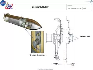
4. Reactor Coolant Pump Design • 2 reactor coolant pumps are attached directly to each steam generator channel head with the motor located below the channel head to simplify the loop piping and eliminate fuel uncover during small loss-of-coolant accidents. • Each reactor coolant pump includes sufficient internal rotating inertia to provide a flow coastdown to avoid departure from nucleate boiling following a loss of reactor coolant flow accident.
6. Pressurizer Design • The power-operated relief valve function is not required nor provided. So pressurizer relief tank is not applied.
7. Safety system (1/5) • The most notable feature of safety design for AP1000 can be seen in the passive safety system; they require no operator action for 72 hours after an accident, and maintain core and containment cooling for a protracted time without ac power; • There are two trains which inject boron water directly into downcomer. Each train includes: • - 01 Core Makeup Tank (high pressure injection), uses fail open AOV. • - 01 Accumulators (intermediate pressure injection), uses check valves. • - 01 injected line from Incontainment Refueling Water Storage Tank (IRWST) (low pressure), uses Squibs and check valves.
7. Safety system (3/5) • ADS uses MOV for valve1/2/3 and Squibs for valve 4 • Passive Residual Heat Removal (Post-accident Recovery) normally isolated by two AOVs, fail open • Opening 1 AOV actuates RCS cooling via natural circulation • AOVs actuated by PMS and by DAS • IRWST absorbs heat – Takes ~ 2 hours to heat up to saturated –Steaming is condensed by PCS and returned to IRWST by gutter AP1000 Passive Decay Heat Removal
7. Safety system (4/5) • Core Makeup Tanks: • Accumulators:
7. Safety system (5/5) • Incontainment Refueling Water Storage Tank (IRWST): • Passive Residual Heat Removal (PRHR):
8. Containment Design • The containment vessel is made of steel. • In case of accident, it is cooled by circulating air through Air Baffle passing between the containment vessel and the outer building surrounding the containment vessel make air as ultimate heat sink. • Annular gravity drain water tanks installed on the roof of the outer building spray water down onto upper part of the vessel. These tanks have the capacity to supply water for 3 days, and resupply though operation keep temperature and pressure of the containment below design values. • The secondary containment only around containment penetration area
Appendix: ECCS comparison • ECCS comparison between different types of pressured water reactor
Thanks for your attention! • Reference: • Westinghouse Electric Company, AP 1000 Standard Combined License Technical Report , DCP/NRC 1749, June 5, 2006. • The Westinghouse AP1000 Advanced Nuclear Plant ,Westinghouse Electric Co., LLC, 2003. • EVN, Final report (draft version ), AP1000 basic design, 2013.