Download
1 / 28
280 likes | 392 Views
Recent results of the ATLAS Barrel Combined Test-beam. Marco Delmastro. (on behalf of the ATLAS liquid Argon group) Università degli Studi di Milano and INFN (Milano, Italy) CERN (Geneva, Switzerland).

E N D
Recent results of the ATLAS Barrel Combined Test-beam Marco Delmastro (on behalf of the ATLAS liquid Argon group) Università degli Studi di Milano and INFN (Milano, Italy) CERN (Geneva, Switzerland) From “digits” to “raw” energy: the electronics calibration of the LAr electromagnetic calorimeter Description of electrons in the detector: data vs. Monte-Carlo comparison Combined studies with the electromagnetic calorimetry Converted photon reconstruction (tracker+EMC) CALOR 2006 - Recent results of the ATLAS combined test-beam
Other related presentations at CALOR 2006 • General description of the ATLAS LAr electromagnetic calorimeter: • Martin Aleksa: “The ATLAS Liquid Argon Calorimeter: Construction, Integration, Commissioning” • Uniformity of the response to electrons: • Irena Nikolic: “Recent Results on the Uniformity of the Liquid Argon Calorimeter Measured in Test Beams” • Linearity of the response to electrons: • Walter Lampl: “Studies of the Linearity of the ATLAS Electromagnetic Calorimeter Response” • Response to pions: • Vincent Giangiobbe: “Studies of the response of the ATLAS barrel calorimeters to pions using 2004 combined test beam data” CALOR 2006 - Recent results of the ATLAS combined test-beam
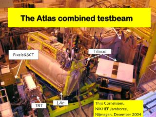
Muon System MDT-RPC BOS Tile HCAL LAr EMC Tile HCAL TRT ATLAS Barrel Combined Test-beam 2004 • Drift chambers: beam position • Scintillators: trigger • Calorimeters on moving table • H8 beam: e, , , and p • Energy: 1 to 350 GeV CALOR 2006 - Recent results of the ATLAS combined test-beam
sampled at 40 MHz and digitised Time Amplitude ( Energy) Optimal Filtering Coefficients Pedestal subtracted ADC to GeV (Ramps) Pedestals Energy Raw Samples LAr electronics calibration:From digits to “raw” energy The ionization signal is sampled every 25 ns by a 12 bits ADC in 3 gains. 6 samples are recorded at the CTB for redundancy (5 at ATLAS). Energy is reconstructed offline (online in ROD at ATLAS). CALOR 2006 - Recent results of the ATLAS combined test-beam
ADC MeV conversion response to current pulse pedestals and noise • All cells are pulsed with a known current signal: • A delay between calibration pulses and DAQ is introduced • The full calibration curve is reconstructed (Δt=1ns) • FEB are read with no input signal to obtain: • Pedestal • Noise • Noise autocorrelation (OFC computation) F = ADC2DAC DAC2A A2MeV fsamp • Scan input current (DAC) • Fit DAC vs ADC curve with a second order polynomial, outside of saturation region ADC ADC DAC Time (ns) Every change of cabling Every 8 hours Every 8 hours LAr electronics calibration:LAr electronic calibration runs CALOR 2006 - Recent results of the ATLAS combined test-beam
LAr electronics calibration:Pedestals and noise • Pedestal and noise levels are measured regularly (every 8 hours) • Measured with two approaches: • Dedicated “pedestal” runs (the FEBs are read without calibration signal or beam) • Random triggers during standard physics runs • Stability is very good (<1ADC), small temperature variations are easily corrected for • Noise and coherent noise are as expected • Coherent noise was particularly high in the pre-sampler FEB, related to a unidentified 2.5 MHz noise source CALOR 2006 - Recent results of the ATLAS combined test-beam
LAr electronics calibration:ADC MeV conversion (1) • Other (global) conversion factors: • DAC2A: from calibration boards and injection resistance data • A2MeV: computed from detailed simulation of charge collection in accordion gaps • fsamp: computed from simulation • Electronic gain of each channel is measured regularly (every 8 hours) • The DAC versus ADC curve is fitted with a second order polynomial • DAC = F0 + F1 · ADC + F2 · ADC2 F1 Injected DAC value CALOR 2006 - Recent results of the ATLAS combined test-beam
LAr electronics calibration:ADC MeV conversion (2) • The electronic gains is very stable: we observed variations up to a few permil • A clear temperature dependence was observed… • … and is corrected for in offline reconstruction thanks the excellent time granularity of the conditions database • Integral non-linearity of the readout remains below 0.1% as required and measured on test bench CALOR 2006 - Recent results of the ATLAS combined test-beam
Ionization signal prediction LAr electronics calibration:Optimal Filtering Coefficients • The use of OF reconstruction allows to • Minimize noise contributions (at CTB only electronic noise, at ATLAS would include pile-up) • Minimize jitter-related effects • OFC computation implies the knowledge of: • noise autocorrelation: • computed from pedestal data • normalized ionization pulse: • predicted from the corresponding calibration profiles according to the electrical model of the readout cell • Predicted pulses includes the correction for the distortion introduced by the electrical properties of the cells At the test-beams particles are asynchronous w.r.t. the DAQ clock: more than one OFC set, chosen according to an external time information (TDC) calibration and ionization pulses are different… … and are injected in different places on the detector CALOR 2006 - Recent results of the ATLAS combined test-beam
Pulse Pattern Response Pattern LAr electronics calibration:Cross-talk effects • The EMC cells share part of their collected current because of cross-talk • In general the effect is negligible, and compensated by the clustering algorithm • The effect is non negligible for the first sampling • The actual electronic gain is overestimated (~9%) • The pulse shapes obtained injecting the calibration current are “wrong” w.r.t. the one generated by a particle shower (cluster) • If these shapes are directly used to compute OFC, the use of these “wrong” OFC lead to a underestimation of the ADC peak (~1-3%) • The combined effects lead to a global overestimation of the first sampling cluster energy of ~7% • We have an effective recipe to treat the effect (gain correction + proper OFC) CALOR 2006 - Recent results of the ATLAS combined test-beam
Description of electrons in the detector: Data vs. Monte-Carlo (E < 9 GeV) • A good description of the energy deposits in the EMC is crucial to obtain the proper energy scale calibration • see W. Lampl talk in this session for details… • Two simulation for two different beam-line setups • “Very Low Energy” (1-9 GeV) • momentum selection is done very close to the CTB trigger • E > 9GeV (9 GeV –180 GeV) VLE: very good description of energy deposits in each EMC layers E = 9 GeV Similar good agreement results down to E = 2 GeV CALOR 2006 - Recent results of the ATLAS combined test-beam
Data PS S1 MC E=20GeV S2 S3 PS+S1+S2+S3 Description of electrons in the detector: data vs. Monte-Carlo (E > 9 GeV) E > 9 GeV: very good description of energy deposits in each EMC layers Similar good agreement results up to E = 180 GeV CALOR 2006 - Recent results of the ATLAS combined test-beam
converted 180 GeV e+ LAr EMC MBPSID Bz Pixel By SCT e+ e- pair emitted (6 mm Pb target) TRT e+ (E130 GeV) e+e- pair Performances of the electromagnetic calorimetry at the CTB:Converted photon reconstruction • CTB photon run setup • Topological clustering is used to reconstruct 3 objects in EMC: • main e+ • e+e- pair from converted • Next step: combine with tracker, compute E/p CALOR 2006 - Recent results of the ATLAS combined test-beam
■ All conversions ■ 3 clusters in EMC Copper foil Magnetic field MC Data MC Data Performances of the electromagnetic calorimetry at the CTB:Converted photon reconstruction • Backtracking of e+e- pair nicely indicates the pixels and SCT layers as conversion points • A good association between clusters in EMC and conversion positions is found • First measurement of E/p is obtained, agreement between data and MC is good! CALOR 2006 - Recent results of the ATLAS combined test-beam
Conclusions • The 2004 ATLAS CTB was an unprecedented occasion to exercise the electronics calibration of the LAr electromagnetic calorimeter • The full electronic calibration chain was implemented • Performances of the ATLAS LAr final electronics were studied, requirements • All the EMC electronics calibration procedures have been implemented in the ATLAS reconstruction software, system is ready for full EMC commissioning (summer 2006) and ATLAS data taking • The response of the detector to electrons is very well understood • Very good agreement between data and Monte-Carlo in the different beam-line setups • Simulation can be used to compute calibration weights (see other talks in this session) • Combined studies are ongoing, first results are very encouraging CALOR 2006 - Recent results of the ATLAS combined test-beam
Additional slides for curious kids CALOR 2006 - Recent results of the ATLAS combined test-beam
Optimal filtering coefficients (1) Choose coefficients for the expressions: such to minimize and with the constraints: , , noise autocorrelation function CALOR 2006 - Recent results of the ATLAS combined test-beam
Optimal filtering coefficients (2) Time equations: Peak equations: Solve with Lagrange multipliers: CALOR 2006 - Recent results of the ATLAS combined test-beam
local constant term < 0.5% (Dh£Df = 0.2£0.4) LAr electronic calibration strategy (1) A known exponential current pulse is injected at the MB level… … and reconstructed through the full readout chain. The actual gain of each readout channel is computed. • The shaper output of the ionisation and calibration signal is different! • Injected signal shape • Different Injection point The triangular ionisation signal is generated at the LAr gap level. CALOR 2006 - Recent results of the ATLAS combined test-beam
triangularionization signal: readout current-to-voltage transfer function: LAr electronic calibration strategy (2) “exponential” calibration signal : calibration signal: ionization signal: CALOR 2006 - Recent results of the ATLAS combined test-beam
LAr electronic calibration strategy (3) In order to complete the cell equalization, the readout gain computed with the calibration signal… … is to applied to an ionisation signal that has been corrected! Injection point correction: LC Injected signal shape difference correction: Td, fstep, tcali The triangular ionisation pulse generated at the LAr gap level is “normalized” when it corresponds to a unitary calibration pulse injected at the MB level… CALOR 2006 - Recent results of the ATLAS combined test-beam
Residual Time Offset trec-toffset (ns) OFC time bin φphase <t> = 0 =1.5ns LAr electronics calibration:OFC Time Tuning at CTB cubic fit time • At 2004 CTB particles are asynchronous w.r.t. the DAQ clock… • More than one OFC set is needed! • corresponding to different portions of the pulse • The good OFC set is chosen according to an external time information (TDC) providing phase • The global trigger setup changed frequently (~10 times!) • it is has been necessary to implement a “timing offsets” mechanism to choose the proper OFC set in each period… • toffset= phase+ tFEB + tglobal • Offsets (tFEB, tglobal) have been computed using an iterative procedure exploiting the timing information provided by the OFC reconstruction • tFEB: FEB timing (when the signal is sampled) • tglobal: Global trigger timing changes CALOR 2006 - Recent results of the ATLAS combined test-beam
Difference w.r.t. reference pedestal run as a function of the event (< 3 ADC) Average value as saved in conditions database LAr electronics calibration:Pedestals temperature variation • In general a very good stability of pedestals was observed… • … but the temperature dependence may become important in case of cooling problems • FEC cooling was not the ATLAS final system, such an important correction is not expected at ATLAS • The effect is small, but since we are looking for precision, we uses pedestals from random trigger varying during a run CALOR 2006 - Recent results of the ATLAS combined test-beam
LAr electronics calibration:Cross talk correction in the EMC first sampling • Prescription • Electronic gain correction • Ration between delay pulse peaks without an with X-talk prescription • OFC correction • Use cross-talk corrected calibration pulses to predict physics pulses, from which compute OFC CALOR 2006 - Recent results of the ATLAS combined test-beam
C6 Target B1 B2 B2 B1 B1 B2 C9 B3 B4 B4 B3 B3 B4 T4 DP/P~1% C3 ~27mm/% H8 beam line -100m NA45 Trig Quads ATLAS 0.12±0.03X0 0.13X0 Momentum selection Focusing -27 m -310 m -140 m Trigger acceptance depends on energy loss and angular distribution of electrons. Acceptance functions have been produced and will be tested with data in combined runs. Inner Detector an important player here. CALOR 2006 - Recent results of the ATLAS combined test-beam
H8 G4 simulation setup CALOR 2006 - Recent results of the ATLAS combined test-beam
G4 (ADC2MeV G4v4.8) / (ADC2MeV G4v4.7) Measured Matched Tuned on high energy run Losses at φ=0 due to non-modelling of the PS module crack. EMC G4 simulation details Data factors: PS Correction = 1235/1149 Strip X-talk Correction = 0.91 MC factors: EM global scale = 0.975 PS scale = 0.946 CALOR 2006 - Recent results of the ATLAS combined test-beam
Back-tracking data quality • Initial track parameters are obtained from the input TRT track • Field integral information is used to make a momentum estimate • Actual tracking is obtained using the xKalman technique CALOR 2006 - Recent results of the ATLAS combined test-beam