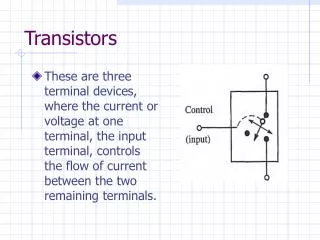
Output Transistors
Output Transistors. Current gain / input impedance is a vital parameter of a power amplifier. In the class A analysis, the load impedance is scaled by a factor of b . High power transistors often have a value of b of the order of tens rather than hundreds. Multiple Transistor Units.

Output Transistors
E N D
Presentation Transcript
Output Transistors • Current gain / input impedance is a vital parameter of a power amplifier. • In the class A analysis, the load impedance is scaled by a factor of b. • High power transistors often have a value of b of the order of tens rather than hundreds.
Multiple Transistor Units To realise a high current gain with low b transistors, use two cascaded emitter follower stages.
Darlington Pair Darlington Pair configuration is available in a single integrated package. VBE is double that of a normal transistor. b is typically between 1000 & 10000.
Efficiency • The efficiency of a power amplifier is the ratio between the power delivered to the load and the power drawn from the supplies. • Power supply requirements and transistor power dissipation ratings depend on the efficiency.
Class A Amplifier Efficiency To calculate efficiency, must calculate load power, PL, and the supplied power, PS.
Maximum output voltage swing is ±VS. Maximum output current swing is ±IE. So : Amplifier efficiency : So, peak efficiency is when A is at its maximum. Worst efficiency is when A = 0.
Class A Efficiency • In practice, the theoretical peak value of A would not be reached without distortion. • Practical maximum efficiency is between 10 and 20 %. • Very low figure, only suitable for low power applications.
Power Dissipation • All power which is not delivered to the load must be dissipated by the output device(s) in the form of heat. • As a result, the temperature of the device rises. • Temperature rise changes the properties of a transistor and may, in extreme cases, destroy it.
Transistor Power Dissipation Ambience / Air, TA Case, TC Power dissipation Junction, TJ Heat only travels from a hot to a cold body Þ TJ > TC > TA Rate of transfer is proportional to temperature difference (and vice versa)
Thermal Resistance Temperature difference between the junction and ambience depends on the power dissipation and the thermal resistance between them. qJA is the thermal resistance between the junction and ambience measured in °C per Watt.
Power-Derating Curve Junction temperature must not exceed Tjmax. Also, power dissipation must not exceed PD0. Combining these limitations gives the power derating curve. PDmax PD0 0 TJmax TA0 TA
Using the Power Derating Curve Example : TIP 120 PDmax [W] 2 1.6 0 25 50 150 TA [°C]
Increasing Power Dissipation • The only fixed point on the power-derating curve is TJmax. • To increase power dissipation, slope of power-derating curve must be steeper. • Thermal resistance must be lowered.
Heat-Sinks qJA can be broken down into a pair of series resistances. qJC = thermal resistance between junction and case (fixed) qCA = thermal resistance between case and ambience. qCA can be lowered by increasing the surface area of the transistor case, i.e. by adding a heat-sink.
Example – TIP 120 PDmax [W] PDmax [W] 5 2 0 0 25 150 TA [°C] 25 150 TA [°C] No heat-sink, qJA = 62.5 °C/W With heat-sink, qJA = 25 °C/W
Summary • High current gain transistors can be synthesised using the Darlington pair. • Class A amplifiers may be simple and linear, they are also highly inefficient. • Inefficiency leads to power dissipation – potential thermal problems. • Power dissipation must always be considered when designing power amplifiers.