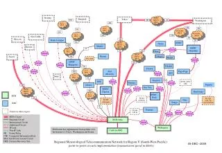
Short Circuit Studies
Short Circuit Studies. Indonesia Clean Energy Development (ICED) project Indonesia Wind Sector Impact Assessment Presented by: Dr. K. Balaraman, Makassar, February 17 to 21, 2014. Short circuit study requirements:. Determining the fault level at buses Selection of breaker ratings


Short Circuit Studies
E N D
Presentation Transcript
Short Circuit Studies Indonesia Clean Energy Development (ICED) project Indonesia Wind Sector Impact Assessment Presented by: Dr. K. Balaraman, Makassar, February 17 to 21, 2014
Short circuit study requirements: • Determining the fault level at buses • Selection of breaker ratings • Protective device co-ordination
Symmetrical components • Unbalanced system of ‘n’ related phasors can be resolved to ‘n’ system of balanced phasors • In each balanced phasor, angle between two phasors and magnitude of each phasor are equal • Phase Quantities: Ia , Ib & Ic and • Sequence components are: • Ia1 stands for Positive sequence current • Ia2 stands for Negative sequence current • Ia0 stands for Zero sequence current.
= Sequence components • Ia1, Ib1 & Ic1 : Same phase sequence as Ia, Ib & Ic • Ia2, Ib2, & Ic2: Opposite phase sequence as Ia, Ib and Ic • Ia0, Ib0, & Ic0 : All in-phase
Therefore no zero sequence exists in line voltage phasor. Since phase voltage sum is not always zero, in the phase voltage phasor, the zero sequence voltage exists.
Sequence Currents Delta Connection Ia+ Ib + Ic= 0 Therefore no zero sequence current flows into delta connection.
Star grounded Star connection Ia+Ib+Ic may not be zero. Hence path always exists for zero sequence currents. Ia+Ib+Ic = 0, There fore no zero sequence current flows into star connection
Star - Delta +ve and -ve Zero Transformer sequence impedance diagram
Star grounded-Delta +ve and -ve Zero Transformer sequence impedance diagram
Zaa a a’ Zbb b b’ Zcc c c’ Sequence Impedance Let Zaa = Zbb = Zcc = Zs and Zab = Zac = Zba = Zbc = Zca= Zcb= ZmTsp Vs = [Z] . Tsp.Is
é ù é ù é ù é ù é ù 1 1 1 V Z Z Z 1 1 1 I 1 1 a s m m a ê ú ê ú ê ú ê ú ê ú = 2 2 a a 1 V Z Z Z a a 1 I ê ú ê ú ê ú ê ú ê ú 2 2 a m s m a ê ú ê ú ê ú ê ú ê ú 2 2 a a 1 V Z Z Z a a 1 I ë û ë û ë û ë û ë û 0 0 a m m s a - é ù é ù é ù V Z Z 0 0 I 1 1 a s m a ê ú ê ú ê ú = - V 0 Z Z 0 I ê ú ê ú ê ú a 2 s m a 2 ê ú ê ú ê ú + V 0 0 Zs 2 Z I ë û ë û ë û 0 0 a m a - é ù Z Z 0 0 s m ú ê = = - Z Z 0 Z Z 0 ê ú 1 , 2 , 0 s s m ê ú + 0 0 Z 2 Z ë û s m
Rotating Machines • Za,b,c is not symmetric. Even then, the Z1,2.0 is diagonalized Exercise: • Find the expression for Z1,2,0 • and Prove that it is a diagonal matrix:
I a1 a Reference Bus Z 1 - E a E a V a1 + Z 1 E E c b Z 1 a Z I 1 b1 I b a1 V = E - I Z a1 a a1 1 I c1 c Positive Sequence Network
Generator impedance for fault study : • Transient (xd’) or sub-transient ( xd”) is considered for positive sequence • X2 i.e. Negative sequence which is close to xd”. (Approximately) • X0 is small 0.1 to 0.7 times xd” Typical values on own rating: Xd 100 to 200 % Xq 60 to 200 % Xd’ 21 to 41 % Xd” 13 to 30 % X2Xd”
Transmission line: • Positive sequence impedance = Negative sequence impedance • Zero sequence impedance depends upon: Return path, Ground wires and Earth resistively • Zero sequence reactance is approximately 2 - 2.5 times positive sequence impedanceR0 is usually large. May be 5 to 10 times also • B0 is 65 to 80 % of B positive sequence Transformers : • All are equal i.e. Zpt= Znt = Zztfor transformer
Fault Representation Va1 = Vf- Z1.Ia1 Va2 = -Z2 . Ia2 Va0 = - Z0 . Ia0
Three phase fault representation Vab = 0 Va = 0 Va1 = 0 Vbc = 0 Vb = 0 Va2 = 0 Vca = 0 Vc = 0 Va0 = 0
Ia1 = Vf Z1 , Ia2 = 0 , Ia0 = 0 Ia = Ia1 Ib = a2Ia1 Ic = aIa1 Ia = Ib = Ic
a V = 0 a b I = 0 c b I I I = 0 a b c I c Single line to ground fault representation
é a a 2 ù 1 I I é ù é ù 1 1 a a ê ú ê ú ê ú 2 = I 1 a a I ê ú ê ú ê ú 2 a b 3 ê ú ê ú ê ú 1 1 1 I I û ë û ë 0 a c = = I I I 1 2 0 a a a V é ù V I 0 é ù é ù é ù Z 0 f 1 1 a 1 a ê ú ê ú ê ú ê ú = - V 0 0 Z 0 I ê ú ê ú ê ú ê ú 2 2 2 a a ê ú ê ú ê ú ê ú 0 0 0 Z V I ë û ë û ë û ë û 0 0 0 a a = - V V Z I 1 1 1 a f a = - V Z I 2 2 2 a a = - V Z I 0 0 0 a a + + = - - - V V V V Z I Z I Z I 1 2 0 1 1 2 2 0 0 a a a f a a a = + + = V V V V 0 Q 1 2 0 a a a a V f = = = I I I 1 2 0 a a a + + Z Z Z 1 2 0 3 V f = I a + + Z Z Z 1 2 0
a b I b c I c Z I f a Fault through Impedance
a V = V b c I a b I = 0 a c I = -I b c I b I c Line to line fault representation Va1 = 1/3 [Va+aVb+a2Vc] = 1/3 [Va+aVb +a2Vb] Va2 = 1/3 [Va+a2Vb+aVc] = 1/3 [Va+a2Vb+aVb] Va1 = Va2
V f \ = = - = = I and I I , I 0 , V 0 ( ) a 1 a 2 a 1 a 0 a 0 + Z Z 1 2 Ia0 = 1/3 (Ia +Ib +Ic) = 1/3 (Ib - Ib) = 0 Ia1 = 1/3 (aIb+a2Ic) = 1/3(aIb-a2Ib) Ia2 = 1/3 (a2Ib + aIc) = 1/3 (a2Ib-aIb) Ia1 = -Ia2 Va1 = Vf - Z1Ia1 Va2 = Z2Ia2 = Va1 = Vf - Z1Ia1 Z2Ia1 = Vf - Z1Ia1
a I a b c I I b c Z f Fault through impedance
é ù 2 1 a a é ù é ù V V 1 ê ú a 1 a ê ú ê ú 2 = ê ú V 1 a a 0 ê ú ê ú a 2 3 ê ú ê ú ê ú V 1 1 1 0 ë û ë û ê ú a 0 ë û 1 1 1 = = = V V , V V , V V a 1 a a 2 a a 0 a 3 3 3 = = V V V a 1 a 2 a 0 Double line to ground fault representation
Ia1 + Ia2 + Ia0 = IA =0 Ia1 = 1/3 (aIb + a2Ic) Ia2 = 1/3 (a2Ib + aIc) Ia0 = 1/3 (Ib + Ic) 1/3(aIb + a2Ic) + 1/3(a2Ib + aIc) + 1/3(Ib +Ic) = 0 aIb + a2Ic + a2Ib + aIc + Ib + Ic = 0 • Va1 = Vf - Z1Ia1 • Va2 = - Z2Ia2 • Va0 = - Z0Ia0 • Va1 = Va2 = Va0 • Vf - Z1Ia1 = - Z2Ia2 - Z0Ia0 • V f = I 1 a é ù æ ö Z Z + ç ÷ 2 0 Z ê ú 1 + è ø Z Z ê ú ë û 2 0
V f V V V a1 a2 a0 Z Z Z 1 0 2 I I I a2 ao a1 V f = I 1 a æ ö ' ' Z Z + ' ç ÷ 2 0 Z 1 + ' ' è ø Z Z 2 0 = + ' Z Z Z 1 1 f = + ' Z Z Z 2 2 f = + + ' Z Z Z 3 Z 0 0 f g Fault through impedance:
a a’ b b’ c c’ a a ' ' - = = V V Z I Z I é ù 2 1 a a é ù é ù i k aa a aa f I I ê ú a 1 a 1 ê ú ê ú 2 = ê ú I 1 a a 0 ê ú ê ú a 2 3 ê ú ê ú ê ú I 1 1 1 0 ë û ë û ê ú a 0 ë û 1 1 = = = = I I I I I a 1 a 2 a 0 a f 3 3 Open in phase B & C Ib = 0 and Ic = 0
Vkl is the Thevenin’s equivalent voltage, once the line is removed between buses k & l Solution Methodology: • 1. Do the load flow with the line isolated • 2. Then insert the line with two phase open and perform short circuit study
l 1 1 1 1 1 = + - - + Z Z Z Z Z Z 1 kk ll lk kl f l 2 2 2 2 2 = + - - + Z Z Z Z Z Z 2 kk ll lk kl f l 0 0 0 0 0 = + - - + Z Z Z Z Z Z 0 kk ll lk kl f ' Z 2 1 0 = I I . f f ' ' + Z Z 0 2 1 ' I . Z 0 f 2 = I f ' ' + Z Z 0 2 Open in phase A • Ia = 0 • Similar type of analysis like double line fault • Voltage is between two nodes, rather than between node and ground • Impedance is the Thevenin’s equivalent impedance between nodes.
Solution methodology • Form the Y bus for +ve, -ve and zero sequence • Do the LU factorisation for +ve, -ve and zero sequence • To find the driving point impedance in fault study, particular row or column of Z bus is required Consider, Yx = z x=Y-1z x= Z.z Let z have 1 in pth location and 0, at all other location
é ù é ù Z Z Z Z Z L é ù 0 11 12 1 p 1 n 1 p ê ú ê ú ê ú Z Z Z Z Z 1 L ê ú ê ú ê ú p 1 p 2 pp pn pp = = x ê ú ê ú ê ú M M M ê ú ê ú ê ú ê ú ê ú 0 Z Z Z Z Z ë û L ë û ë û n 1 n 2 np nn np \ = Yx z Solution methodology • Pass in z, 1.0 for the desired bus and 0 else where. • Call LU solution - x will be the desired column of Z bus. • Find the sequence fault current I1f, I2f and I0f. • Determine the post fault bus voltage
[Vf] = [Z] [If1] = [Z] {[I0] - [If]} = [Z] [I0] + [Z][-If] = [V0] + [V] V = [Z] [-If] Y[V] = [-If] Solve V using LU solution. Above can be written as : [Y]p[V]p = [-If]p , p: positive sequence and similarly for other sequences.
é ù 0 ê ú 0 ê ú ê ú M ê ú M ê ú [ ] ê ú - = - I k I f f ê ú p ê ú M ê ú + I ú ê f ê ú M ê ú 0 ë û é ù 0 ê ú 0 ê ú ê ú : [ ] ê ú - = - I I ê ú f f p : ê ú ê ú 0 ê ú ê ú ë û p For faults other than open fault, For open fault, between k & l,
High resistance X ”=24% d Grounding 50 MVA ,13.8/138 kV 11% G F 40 Mile, 0.77 Ohm/mile X. X0 = 3X E D 100 MVA ,138/13.8 kV 11% C B 20% on 100 MVA X ”= 9% d A Example:
Grounding practice in Power System Advantages of ungrounded system : • Ground connection normally doesn’t carry current. Hence elimination saves the cost. • Current can be carried in other phases, with fewer interruptions.
Limitations of ungrounded system • With the increase in voltage and line length current has increased and self clearing nature advantage couldn’t be seen • Arcing ground : Phenomena of alternate clearing and re-striking of the arc, which cause high voltage (surge and transient) • If grounded, the insulation can be graded in transformer from line to neutral, there by reducing the cost • In case of ungrounded system, influence on communication lines is more. • Ground current can’t be limited
a b c 3.0 1.73 1.73 0.0 Ungrounded system Perfectly transposed line : Neutral of transformer is at zero potential. Un-transposed line : Neutral is shifted. Capacitance grounded : Perfectly transposed line.
Resistance grounded system : • The resistance to neutral limits ground current. Selection of resistance value: • Amount of ground fault current Power loss in resistor during ground fault • Power loss: usually expressed as a percentage of system rating
R X = 8% g X = 16 % g ´ 3 100 3 300 = = = I f + + + + + + Z Z Z j 24 j 24 3 R j 8 3 R j 56 1 2 0 2 æ ö 300 2 = = ç ÷ Power Loss I R . R f + è ø 3 j 56 R Z1 = 24% , Z2=24% , Z0=3R+j8
2 I R f = percentage of 3 phase system kVA rating 3 If : in pu, R : in pu For three phase system, power loss R is in percent p.u. Maximum power loss = ? Selection : How much be the value of ground fault current ? What should be the percent power loss in the ground resistance ?