Interconnection Networks
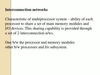
Interconnection Networks . Overview. Physical Layer and Message Switching Network Topologies Metrics Deadlock & Livelock Routing Layer The Messaging Layer. Interconnection Networks. Fabric for scalable, multiprocessor architectures


Interconnection Networks
E N D
Presentation Transcript
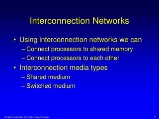
Overview • Physical Layer and Message Switching • Network Topologies • Metrics • Deadlock & Livelock • Routing Layer • The Messaging Layer
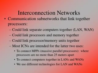
Interconnection Networks • Fabric for scalable, multiprocessor architectures • Distinct from traditional networking architectures such as Internet Protocol (IP) based systems • We are interested in applications to large clusters as well as embedded systems
CLUX: A Beowulf Cluster Interconnection Network Cables Myrinet Switch Images from the Clux cluster at http://www.fyslab.hut.fi/clux/
The Practical Problem From: Ambuj Goyal, “Computer Science Grand Challenge – Simplicity of Design,” Computing Research Association Conference on "Grand Research Challenges" in Computer Science and Engineering, June 2002
Example: Embedded Devices picoChip: http://www.picochip.com/ • Issues • Execution performance • Power dissipation • Number of chip types • Size and form factor PACT XPP Technologies: http://www.pactcorp.com/
Messaging Hierarchy Routing Layer Where?: Destination decisions, i.e., which output port Switching Layer When?: When is data forwarded Physical Layer How?: synchronization of data transfer • This organization is distinct from traditional networking implementations • Emphasis is on low latency communication • Only recently have standards been evolving • Infiniband: http://www.infinibandta.org/home
The Physical Layer Data • Data is transmitted based on a hierarchical data structuring mechanism • Messages packets flits phits • While flits and phits are fixed size, packets and data may be variable sized Packets checksum header Flit: flow control digit Phit: physical flow control digit
Flow Control • Flow control digit: synchronized transfer of a unit of information • Based on buffer management • Asynchronous vs. synchronous flow control • Flow control occurs at multiple levels • message flow control • physical flow control • Mechanisms • Credit based flow control
Switching Layer • Comprised of three sets of techniques • switching techniques • flow control • buffer management • Organization and operation of routers are largely determined by the switching layer • Connection Oriented vs. Connectionless communication
Generic Router Architecture Wire delay Switching delay Routing delay
Virtual Channels • Each virtual channel is a pair of unidirectional channels • Independently managed buffers multiplexed over the physical channel • De-couples buffers from physical channels • Originally introduced to break cyclic dependencies • Improves performance through reduction of blocking delay • Virtual lanes vs. virtual channels • As the number of virtual channels increase, the increased channel multiplexing has two effects • decrease in header delay • increase in average data flit delay • Impact on router performance • switch complexity
Circuit Switching Header Probe Acknowledgment Data • Hardware path setup by a routing header or probe • End-to-end acknowledgment initiates transfer at full hardware bandwidth • Source routing vs. distributed routing • System is limited by signaling rate along the circuits Link tr ts tsetup tdata Time Busy
Message Header Message Data Link tr tpacket Time Busy Packet Switching • Blocking delays in circuit switching avoided in packet switched networks full link utilization in the presence of data • Increased storage requirements at the nodes • Packetization and in-order delivery requirements • Buffering • use of local processor memory • central queues
Virtual Cut-Through Packet Header Message Packet cuts through the Router • Messages cut-through to the next router when feasible • In the absence of blocking, messages are pipelined • pipeline cycle time is the larger of intra-router and inter-router flow control delays • When the header is blocked, the complete message is buffered • High load behavior approaches that of packet switching tw Link tblocking tr ts Time Busy
Wormhole Switching Header Flit • Messages are pipelined, but buffer space is on the order of a few flits • Small buffers + message pipelining small compact buffers • Supports variable sized messages • Messages cannot be interleaved over a channel: routing information is only associated with the header • Base Latency is equivalent to that of virtual cut-through Link Single Flit tr ts twormhole Time Busy
Comparison of Switching Techniques • Packet switching and virtual cut-through • consume network bandwidth proportional to network load • predictable demands • VCT behaves like wormhole at low loads and like packet switching at high loads • link level error control for packet switching • Wormhole switching • provides low latency • lower saturation point • higher variance of message latency than packet or VCT switching • Virtual channels • blocking delay vs. data delay • router flow control latency • Optimistic vs. conservative flow control
Motivation • Crossbars provide full connectivity among ports, but cost and complexity grow quadratically in the number of ports • Buses provide minimal connectivity and do not provide scalable performance • Network topologies span a spectrum of solutions that trade-off cost, performance (latency & bandwidth), reliability, and implementation complexity
Direct Networks • Fixed degree • Modular • Topologies • Meshes • Multidimensional tori • Special case of tori – the binary hypercube
0000 0001 1110 1111 Indirect Networks • Indirect networks • uniform base latency • centralized or distributed control • Engineering approximations to direct networks Multistage Network Backward Forward Fat Tree Network Bandwidth increases as you go up the tree
Switch sizes and interstage interconnect establish distinct MINS Majority of interesting MINs have been shown to be topologically equivalent Specific MINs 000 000 000 000 000 000 001 001 001 001 001 001 010 010 010 010 010 010 011 011 011 011 011 011 100 100 100 100 100 100 101 101 101 101 101 101 110 110 110 110 110 110 111 111 111 111 111 111
Evaluation Metrics • Latency • Message transit time • Determined by switching technique and traffic patterns • Node degree (channel width) • Number of input/output channels • This metric is determined by packaging constraints • pin/wiring constraints • Diameter • Path diversity • A measure of reliability
Evaluation Metrics bisection • Bisection bandwidth • This is minimum bandwidth across any bisection of the network • Bisection bandwidth is a limiting attribute of performance
Latency Under Contention 32-ary 2-cube vs. 10-ary 3 cube
Deadlock freedom can be ensured by enforcing constraints For example, following dimension order routing in 2D meshes Deadlock and Livelock router Virtual Channel
Occurrence of Deadlock 3 1 4 2 • Deadlock is caused by dependencies between buffers
Deadlock Avoidance: Principle • Deadlock is caused by dependencies between buffers
Routing Constraints on Virtual Channels • Add multiple virtual channels to each physical channel • Place routing restrictions between virtual channels
Routing Protocols Routing Algorithms Number of Destinations Unicast Routing Multicast Routing Routing Decisions Centralized Routing Source Routing Distributed Routing Multiphase Routing Implementation Table Lookup Finite State Machine Adaptivity Deterministic Routing Adaptive Routing Progressiveness Progressive Backtracking Minimality Profitable Misrouting Number of Paths Complete Partial Source: J. Duato, S. Yalamanchili, and L. Ni, “Interconnection Networks,” Morgan Kaufman 2003.
Key Routing Categories • Deterministic • The path is fixed by the source destination pair • Source Routing • Path is looked up prior to message injection • May differ each time the network and NIs are initialized • Adaptive routing • Path is determined by run-time network conditions • Unicast • Single source to single destination • Multicast • Single source to multiple destinations
From/to local processor Input queues (virtual channels) Output queues (virtual channels) mux Switch Physical input channels Physical output channels mux Address decoder Generic Router Architecture
The Message Layer • Message layer background • Cluster computers • Myrinet SAN • Design properties • End-to-End communication path • Injection • Network transmission • Ejection • Overall performance
CPU CPU CPU Memory Memory Memory CPU Memory I/O Bus I/O Bus I/O Bus I/O Bus Network Interface Network Interface Network Interface Network Interface Network Cluster Computers • Cost-effective alternative to supercomputers • Number of commodity workstations • Specialized network hardware and software • Result: Large pool of host processors Courtesy of C. Ulmer
CPU NI CPU NI CPU NI X X CPU NI X CPU NI CPU CPU NI NI Myrinet • Descendant of Caltech Mosaic project • Wormhole network • Source routing • High-speed, Ultra-reliable network • Configurable topology: Switches, NICs, and cables Courtesy of C. Ulmer
Fiber Backplane Fiber X X X X Fiber 16 Xbar To Backplane Fiber Fiber Line Cards X X X Fiber X X X X X Line Card Fiber Fiber 16 Port Xbar 8 Hosts / Line Card Myrinet Switches & Links • 16 Port crossbar chip • 2.0+2.0 Gbps per port • ~300 ns Latency • Line card • 8 Network ports • 8 Backplane ports • Backplane cabinet • 17 line card slots • 128 Hosts Courtesy of C. Ulmer
Myrinet NI Architecture • Custom RISC CPU • 33-200MHz • Big endian • gcc is available • SRAM • 1-9MB • No CPU cache • DMA Engines • PCI / SRAM • SRAM / Tx • Rx / SRAM SRAM RISC CPU PCI Host DMA SAN DMA Tx Rx LANai Processor Network Interface Card Courtesy of C. Ulmer
Message Layers Courtesy of C. Ulmer
CPU CPU CPU CPU CPU CPU CPU CPU CPU Cluster Message Layer “Message Layer” Communication Software • Message layers are enabling technology for clusters • Enable cluster to function as single image multiprocessor system • Responsible for transferring messages between resources • Hide hardware details from end users Courtesy of C. Ulmer