Series-RCRE-2
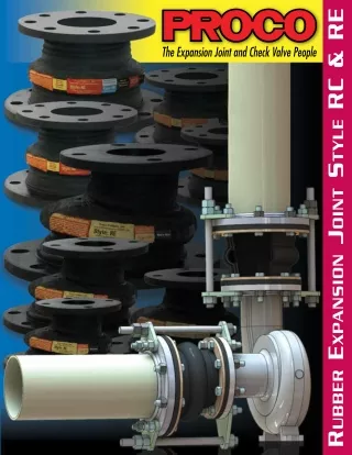
Proco Products, Inc. is the global leader in the design and supply of expansion joints for piping and ducting systems.

Series-RCRE-2
E N D
Presentation Transcript
Proco’s Headquarters Largest Inventory of Expansion Joints and Check Valves 1
Proco Style RC & RE Rubber Joints Proco Style RC & RERubber Expansion Joints are designed for piping systems to absorb pipe movements, relieve stress, reduce system noise/ vibration, compensate for misalignment/offset and to protect rotating mechanical equipment against start-up surge forces. The Style RC-231 concentric rubber expansion joint is a single open wide arch type. Concentric in design, each flange-end shares the same common center-line. The Style RCFA-231 concentric rubber expansion joint is a single filled wide arch design generally used for slurry or abrasive services. This design has 50% less movement than the open arch design. The Style RE-231 eccentric rubber expansion joint is a single open wide arch type. Eccentric in design, the expansion joint body tapers on one side transitioning two different flange sizes. The Style REFA-231 eccentric rubber expansion joint is a single filled wide arch design generally used for slurry or abrasive services. This design has 50% less movement than the open arch design. Also available from Proco Products, Inc. are the old narrow arch styles RC-221, RCFA-221, RE-221 and REFA-221 with shorter overall lengths. Features and Benefits: Absorbs Directional Movement Thermal movements appear in any rigid pipe system due to temperature changes. The Style RC 231 and RE 231 wide arch joints allow for axial compression or axial extension, lateral deflection as well as angular and torsional movements. (Note: Rated movements in this publication are based on one plane movements. Multiple movement conditions are based on a multiple movement calculation. Contact Proco for information when designing multiple pipe movements.) Less Turbulence or Material Entrapment The Style RC 231 and RE 231 expansion joints are manufactured with the integral rubber flange joining the body at a true 90° angle. This ensures the product will install snug against the mating pipe flange free of voids creating less turbulence in the pipe system. For applications where 20% or more solids are present, use the filled arch RCFA 231 and REFA 231 expansion joints for smooth bore transition with no possibility for material entrapment. Absorbs Vibration, Noise and Shock The Proco Style RC 231 and RE 231 rubber expansion joints effectively dampen and insulate downstream piping against the transmission of noise and vibration generated by mechanical equipment. Noise and vibrations caused by equipment can cause stress in pipe, pipe guides, anchors and other equipment downstream. The Style RC 231 and RE 231 expansion joints will help relieve noise and vibration occurrences in a pipe system. Water hammer and pumping impulses can also cause strain, stress or shock to a piping system. Install the Style RC 231 and RE 231 to help compensate for these system pressure spikes. Compensates for Misalignment Rubber expansion joints are commonly used by contractors and plant personnel to allow for slight pipe misalignment during installation of new piping and or replacement applications. (Although rubber expansion joints can be made with permanent offsets, it is suggested that piping misalignments be limited to no more than 1/2 the rated catalog movement. Contact Proco for resultant movement capability.) Wide Service Range and Less Weight Engineered to operate up to 200 PSIG (nominal size dependent) or up to 250°F (elastomer dependent), the Series RC 231 and RE 231 can be specified for a wide range of piping system requirements. The Series RC 231 and RE 231 rubber expansion joints are constructed in various elastomers with rubber impregnated polyester tire cord and ASTM wire to make up the pressure restraining member. This lightweight design installs easily and costs less to ship. Material Identification All RC 231 and RE 231 expansion joints are strip branded with cure dates and elastomer designations. All Neoprene Tube/Neoprene Cover (NN) and Nitrile Tube/Neoprene Cover (NP)elastomer designated joints meet the Coast Guard Requirements and conform to ASTM F 1123-87. Large Inventory Proco Products, Inc. maintains one of the largest inventories of rubber expansion joints in the world. Please contact us for price and availability. NH NN NF NP NR Notes: All Products are reinforced with Polyester Tire Cord 1. Expansion Joint “Cover” can be coated with CSM UV Resistant Coating. 2. All NN & NP elastomer designated joints meet the Coast Guard Requirements and conform to ASTM F 1123-87 and are marked accordingly. 3. Branding Label will be marked as “Food Grade”. 4. All elastomers above are not intended for steam service Table 1: Available Materials • Temperatures For Specific Chemical Compatibilities, See: PROCO “Chemical To Elastomer Guide” Proco Material Code BB Chlorobutyl Chlorobutyl EE EPDM EPDM EQ EPDM FDA-EPDM Neoprene CSM Neoprene Neoprene Neoprene FDA-Neoprene Neoprene Nitrile Neoprene Natural Rubber Maximum Operating Temp. °F (°C) 250° (121°) 250° (121°) 250° (121°) 212° (100°) 225° (107°) 225° (107°) 212° (100°) 180° (82°) Branding Label Color Black Red Red3 Green Blue Blue3 Yellow White F.S.A. Material Class STD. III STD. III STD. II STD. II STD. II STD. II STD. II STD. I Cover 1,2 Elastomer Tube Elastomer Protecting Piping and Equipment Systems from Stress/Motion Information subject to change without notice. 2
Style RC-231 Performance Data Table 2: Sizes • Movements • Operating Conditions • Weights Concentric Joint Size Length From Neutral Position: RC-231 Movement Capability 1 Operating 2 Conditions Weights 3 lbs/(kgs) Neutral Vacuum In. of 7 Hg/(mm of Hg) 26 (660) 26 (660) 26 (660) 26 (660) 26 (660) 26 (660) 26 (660) 26 (660) 26 (660) 26 (660) 26 (660) 26 (660) 26 (660) 26 (660) 26 (660) 26 (660) 26 (660) 26 (660) 26 (660) 26 (660) 26 (660) 26 (660) 26 (660) 26 (660) Thrust Factor 6 4.83 (31) 5.85 (38) 6.97 (45) 8.19 (53) 6.97 (45) 8.19 (53) 9.51 (61) 10.92 (70) 12.43 (80) 14.05 (91) 15.76 (102) 21.06 (136) 25.33 (163) 21.06 (136) 23.15 (149) 25.33 (163) 29.98 (193) 35.03 (226) 35.03 (226) 40.47 (261) 46.30 (299) 52.53 (339) 59.14 (382) 66.15 (427) Nominal I.D. X I.D. (Inch) ±Angular 4 Deflection Degrees Torsional 5 Rotation Degrees Axial Axial Extension Inch/(mm) ±Lateral Deflection Inch/(mm) PSIG / (Bar) Min. (Inch) Max. (Inch) In2 / (cm2) Limit Rods 8 7.0 (3.2) 7.0 (3.2) 8.0 (3.6) 8.0 (3.6) 8.0 (3.6) 8.0 (3.6) 8.0 (3.6) 8.0 (3.6) 8.0 (3.6) 8.0 (3.6) 8.0 (3.6) 12.0 (5.4) 12.0 (5.4) 14.0 (6.4) 14.0 (6.4) 14.0 (6.4) 14.0 (6.4) 14.0 (6.4) 22.0 (10.0) 21.0 (9.5) 22.0 (10.0) 23.0 (10.4) 31.0 (14.1) 31.0 (14.1) Joint/Rings 5.0 (2.3) 6.0 (2.7) 6.0 (2.7) 6.0 (2.7) 7.0 (3.2) 8.0 (3.6) 9.0 (4.1) 9.0 (4.1) 10.0 (4.5) 11.0 (5.0) 12.0 (5.4) 15.0 (6.8) 16.0 (7.3) 15.0 (6.8) 15.0 (6.8) 17.0 (7.7) 17.0 (7.7) 18.0 (8.2) 19.0 (8.6) 19.0 (8.6) 20.0 (9.1) 21.0 (9.5) 25.0 (11.3) 26.0 (11.8) Expansion Compression Inch/(mm) Positive 200 (14) 200 (14) 200 (14) 200 (14) 200 (14) 200 (14) 200 (14) 200 (14) 200 (14) 200 (14) 200 (14) 190 (13) 190 (13) 190 (13) 190 (13) 190 (13) 190 (13) 190 (13) 190 (13) 190 (13) 190 (13) 190 (13) 190 (13) 190 (13) 1.0 (25) 1.0 (25) 1.0 (25) 1.0 (25) 1.4 (36) 1.4 (36) 1.4 (36) 1.4 (36) 1.4 (36) 1.4 (36) 1.4 (36) 1.6 (41) 1.6 (41) 1.6 (41) 1.6 (41) 1.6 (41) 1.6 (41) 1.6 (41) 1.6 (41) 1.6 (41) 1.6 (41) 1.6 (41) 1.6 (41) 1.6 (41) 0.5 (13) 0.5 (13) 0.5 (13) 0.5 (13) 0.7 (18) 0.7 (18) 0.7 (18) 0.7 (18) 0.7 (18) 0.7 (18) 0.7 (18) 0.8 (20) 0.8 (20) 0.8 (20) 0.8 (20) 0.8 (20) 0.8 (20) 0.8 (20) 0.8 (20) 0.8 (20) 0.8 (20) 0.8 (20) 0.8 (20) 0.8 (20) 0.5 (13) 0.5 (13) 0.5 (13) 0.5 (13) 0.5 (13) 0.5 (13) 0.5 (13) 0.5 (13) 0.5 (13) 0.5 (13) 0.5 (13) 0.5 (13) 0.5 (13) 0.5 (13) 0.5 (13) 0.5 (13) 0.5 (13) 0.5 (13) 0.5 (13) 0.5 (13) 0.5 (13) 0.5 (13) 0.5 (13) 0.5 (13) 2 X 1 8 18 25.0 2.0 2 X 1.5 8 18 25.0 2.0 2.5 X 1.5 8 18 20.0 2.0 2.5 X 2 8 18 20.0 2.0 3 X 1 8 18 24.0 2.0 3 X 1.5 8 18 24.0 2.0 3 X 2 8 18 24.0 2.0 3 X 2.5 8 18 24.0 2.0 4 X 2 8 18 18.0 2.0 4 X 2.5 8 18 18.0 2.0 4 X 3 8 18 18.0 2.0 5 X 3 8 18 17.0 2.0 5 X 4 8 18 17.0 2.0 6 X 2 8 18 14.0 2.0 6 X 2.5 8 18 14.0 2.0 6 X 3 8 18 14.0 2.0 6 X 4 8 18 14.0 2.0 6 X 5 8 18 14.0 2.0 8 X 3 8 18 11.0 2.0 8 X 4 8 18 11.0 2.0 8 X 5 8 18 11.0 2.0 8 X 6 8 18 11.0 2.0 10 X 5 10 18 8.0 2.0 10 X 6 10 18 8.0 2.0 See Notes Page 4 3
Table 2: Sizes • Movements • Operating Conditions • Weights Concentric Joint Size Length From Neutral Position: RC-231 Movement Capability 1 Operating 2 Conditions Weights 3 lbs/(kgs) Neutral Vacuum In. of 7 Hg/(mm of Hg) 26 (660) 26 (660) 26 (660) 26 (660) 26 (660) 26 (660) 26 (660) 26 (660) 26 (660) 26 (660) 26 (660) 26 (660) 26 (660) Nominal I.D. X I.D. (Inch) Thrust Factor 6 81.35 (525) 84.50 (545) 101.57 (655) 120.22 (776) 120.22 (776) 140.43 (906) 162.21 (1047) 162.21 (1047) 185.57 (1197) 210.49 (1358) 210.49 (1358) 236.98 (1529) 265.05 (1710) ±Angular 4 Deflection Degrees Torsional 5 Rotation Degrees Axial Axial Extension Inch/(mm) ±Lateral Deflection Inch/(mm) PSIG / (Bar) Min. (Inch) Max. (Inch) In2 / (cm2) Limit Rods 8 32.0 (14.5) 35.0 (15.9) 34.0 (15.4) 29.0 (13.2) 34.0 (15.4) 38.0 (17.2) 31.0 (14.1) 45.0 (20.4) 42.0 (19.1) 43.0 (19.5) 48.0 (21.8) 43.0 (19.5) 39.0 (17.7) Joint/Rings Expansion 30.0 (13.6) 35.0 (15.9) 39.0 (17.7) 42.0 (19.1) 45.0 (20.4) 48.0 (21.8) 55.0 (24.9) 54.0 (24.5) 60.0 (27.2) 62.0 (28.1) 64.0 (29.0) 66.0 (29.9) 70.0 (31.8) Compression Inch/(mm) Positive 190 (13) 190 (13) 190 (13) 190 (13) 130 (9) 130 (9) 130 (9) 115 (8) 115 (8) 115 (8) 115 (8) 115 (8) 115 (8) 1.6 (41) 1.6 (41) 1.6 (41) 1.6 (41) 1.6 (41) 1.6 (41) 1.6 (41) 1.6 (41) 1.6 (41) 1.6 (41) 1.6 (41) 1.6 (41) 1.6 (41) 0.8 (20) 0.8 (20) 0.8 (20) 0.8 (20) 0.8 (20) 0.8 (20) 0.8 (20) 0.8 (20) 0.8 (20) 0.8 (20) 0.8 (20) 0.8 (20) 0.8 (20) 0.5 (13) 0.5 (13) 0.5 (13) 0.5 (13) 0.5 (13) 0.5 (13) 0.5 (13) 0.5 (13) 0.5 (13) 0.5 (13) 0.5 (13) 0.5 (13) 0.5 (13) 10 X 8 10 18 8.0 2.0 12 X 6 10 18 7.0 2.0 12 X 8 10 18 7.0 2.0 12 X 10 10 18 7.0 2.0 14 X 8 10 18 6.0 2.0 14 X 10 10 18 6.0 2.0 14 X 12 10 18 6.0 2.0 16 X 10 10 18 5.0 2.0 16 X 12 10 18 5.0 2.0 16 X 14 10 18 5.0 2.0 18 X 12 10 18 5.0 2.0 18 X 14 10 18 5.0 2.0 18 X 16 10 18 5.0 2.0 NOTES: 1. The RC-231 is available in a Filled Arch configuration. Known as the RCFA-231, this filled arch configuration is designed to eliminate flow turbulence and collection of solids for sludge, slurries or other heavy solids. The RCFA-231 filled arch product is manufactured with a seamless tube and is built as an integral part of the carcass. Although the arch filler is made with a lower durometer rubber, movement ratings of the RCFA-231 are 50% less than the movements listed in the above table. 2. Pressure rating is based on 170˚ F operating temperature with a 4:1 safety factor. At higher temperatures, the pressure rating is reduced slightly. Hydrostatic testing at 1.5 times rated maximum catalogue pressure or design working pressure of pipe system for 10 minutes is available upon request. 3. Weights are approximate and vary due to length. 4. The degree of angular movement is based on the maximum rated extension. 5. Torsional movement is expressed when the expansion joint is at neutral length. 6. Calculation of Thrust (Thrust Factor). When expansion joints are installed in the pipeline, the static portion of the thrust is calculated as a product of the area of the I.D. of the arch of the expansion joint times the maximum pressure (design, test or surge) that will occur in the line. The result is a force expressed in pounds. Take design, surge or test pressure X thrust factor to calculate end thrust. For filled arch configuration use the I.D. of the pipe (D)2 to calculate end thrust. 7. Parts listed at 26” Hg / 660 mm Hg vacuum. Vacuum rating is based on neutral installed length, without external load. Products should not be installed “extended” on vacuum applications. 8. Limit rod unit weight consists of one rod with washers, nuts, and two limit rod plates. Multiply number of limit rods needed for the application (as specified in the Fluid Sealing Association’s Technical Handbook, Seventh Edition or table 4 in this manual) to determine correct weights. 9. For plastic pipe systems utilizing the series RC, consult Proco for design considerations. 10. Larger sizes not shown in brochure are available upon request. “Effective Area” Thrust Factor= sales@procoproducts.com • (800) 344-3246 4
Style RE-231 Performance Data Table 3: Sizes • Movements • Operating Conditions • Weights Eccentric Joint Size Length From Neutral Position: RE-231 Movement Capability 1 Operating 2 Conditions Weights 3 lbs/(kgs) Neutral Vacuum In. of 7 Hg/(mm of Hg) 26 (660) 26 (660) 26 (660) 26 (660) 26 (660) 26 (660) 26 (660) 26 (660) 26 (660) 26 (660) 26 (660) 26 (660) 26 (660) 26 (660) 26 (660) 26 (660) 26 (660) 26 (660) 26 (660) 26 (660) 26 (660) 26 (660) 26 (660) 26 (660) Nominal I.D. X I.D. (Inch) Thrust Factor 6 4.83 (31) 5.85 (38) 6.97 (45) 8.19 (53) 6.97 (45) 8.19 (53) 9.51 (61) 10.92 (70) 12.43 (80) 14.05 (91) 15.76 (102) 21.06 (136) 25.33 (163) 21.06 (136) 23.15 (149) 25.33 (163) 29.98 (193) 35.03 (226) 35.03 (226) 40.47 (261) 46.30 (299) 52.53 (339) 59.14 (382) 66.15 (427) ±Angular 4 Deflection Degrees Torsional 5 Rotation Degrees Axial Axial Extension Inch/(mm) ±Lateral Deflection Inch/(mm) PSIG / (Bar) Max. (Inch) Min. (Inch) In2 / (cm2) Limit Rods 8 7.0 (3.2) 7.0 (3.2) 8.0 (3.6) 8.0 (3.6) 8.0 (3.6) 8.0 (3.6) 8.0 (3.6) 8.0 (3.6) 8.0 (3.6) 8.0 (3.6) 8.0 (3.6) 12.0 (5.4) 12.0 (5.4) 14.0 (6.4) 14.0 (6.4) 14.0 (6.4) 14.0 (6.4) 14.0 (6.4) 22.0 (10.0) 21.0 (9.5) 22.0 (10.0) 23.0 (10.4) 31.0 (14.1) 31.0 (14.1) Joint/Rings 5.0 (2.3) 6.0 (2.7) 3.0 (1.4) 6.0 (2.7) 7.0 (3.2) 8.0 (3.6) 9.0 (4.1) 9.0 (4.1) 10.0 (4.5) 11.0 (5.0) 12.0 (5.4) 15.0 (6.8) 16.0 (7.3) 15.0 (6.8) 15.0 (6.8) 17.0 (7.7) 17.0 (7.7) 18.0 (8.2) 19.0 (8.6) 19.0 (8.6) 20.0 (9.1) 21.0 (9.5) 25.0 (11.3) 26.0 (11.8) Expansion Compression Inch/(mm) Positive 200 (14) 200 (14) 200 (14) 200 (14) 200 (14) 200 (14) 200 (14) 200 (14) 200 (14) 200 (14) 200 (14) 190 (13) 190 (13) 190 (13) 190 (13) 190 (13) 190 (13) 190 (13) 190 (13) 190 (13) 190 (13) 190 (13) 190 (13) 190 (13) 1.0 (25) 1.0 (25) 1.0 (25) 1.0 (25) 1.4 (36) 1.4 (36) 1.4 (36) 1.4 (36) 1.4 (36) 1.4 (36) 1.4 (36) 1.6 (41) 1.6 (41) 1.6 (41) 1.6 (41) 1.6 (41) 1.6 (41) 1.6 (41) 1.6 (41) 1.6 (41) 1.6 (41) 1.6 (41) 1.6 (41) 1.6 (41) 0.5 (13) 0.5 (13) 0.5 (13) 0.5 (13) 0.7 (18) 0.7 (18) 0.7 (18) 0.7 (18) 0.7 (18) 0.7 (18) 0.7 (18) 0.8 (20) 0.8 (20) 0.8 (20) 0.8 (20) 0.8 (20) 0.8 (20) 0.8 (20) 0.8 (20) 0.8 (20) 0.8 (20) 0.8 (20) 0.8 (20) 0.8 (20) 0.5 (13) 0.5 (13) 0.5 (13) 0.5 (13) 0.5 (13) 0.5 (13) 0.5 (13) 0.5 (13) 0.5 (13) 0.5 (13) 0.5 (13) 0.5 (13) 0.5 (13) 0.5 (13) 0.5 (13) 0.5 (13) 0.5 (13) 0.5 (13) 0.5 (13) 0.5 (13) 0.5 (13) 0.5 (13) 0.5 (13) 0.5 (13) 2 X 1 8 18 25.0 2.0 2 X 1.5 8 18 25.0 2.0 2.5 X 1.5 8 18 20.0 2.0 2.5 X 2 8 18 20.0 2.0 3 X 1 8 18 24.0 2.0 3 X 1.5 8 18 24.0 2.0 3 X 2 8 18 24.0 2.0 3 X 2.5 8 18 24.0 2.0 4 X 2 8 18 18.0 2.0 4 X 2.5 8 18 18.0 2.0 4 X 3 8 18 18.0 2.0 5 X 3 8 18 17.0 2.0 5 X 4 8 18 17.0 2.0 6 X 2 8 18 14.0 2.0 6 X 2.5 8 18 14.0 2.0 6 X 3 8 18 14.0 2.0 6 X 4 8 18 14.0 2.0 6 X 5 8 18 14.0 2.0 8 X 3 8 18 11.0 2.0 8 X 4 8 18 11.0 2.0 8 X 5 8 18 11.0 2.0 8 X 6 8 18 11.0 2.0 10 X 5 10 18 8.0 2.0 10 X 6 10 18 8.0 2.0 See Notes Page 6 5
Table 3: Sizes • Movements • Operating Conditions • Weights Eccentric Joint Size Length From Neutral Position: RE-231 Movement Capability 1 Operating 2 Conditions Weights 3 lbs/(kgs) Neutral Vacuum In. of 7 Hg/(mm of Hg) 26 (660) 26 (660) 26 (660) 26 (660) 26 (660) 26 (660) 26 (660) 26 (660) 26 (660) 26 (660) 26 (660) 26 (660) 26 (660) Nominal I.D. X I.D. (Inch) Thrust Factor 6 81.35 (525) 84.50 (545) 101.57 (655) 120.22 (776) 120.22 (776) 140.43 (906) 162.21 (1047) 162.21 (1047) 185.57 (1197) 210.49 (1358) 210.49 (1358) 236.98 (1529) 265.05 (1710) ±Angular 4 Deflection Degrees Torsional 5 Rotation Degrees Axial Axial Extension Inch/(mm) ±Lateral Deflection Inch/(mm) PSIG / (Bar) Min. (Inch) Max. (Inch) In2 / (cm2) Limit Rods 8 32.0 (14.5) 35.0 (15.9) 34.0 (15.4) 29.0 (13.2) 34.0 (15.4) 38.0 (17.2) 31.0 (14.1) 45.0 (20.4) 42.0 (19.1) 43.0 (19.5) 48.0 (21.8) 43.0 (19.5) 39.0 (17.7) Joint/Rings Expansion 30.0 (13.6) 35.0 (15.9) 39.0 (17.7) 42.0 (19.1) 45.0 (20.4) 48.0 (21.8) 55.0 (24.9) 54.0 (24.5) 60.0 (27.2) 62.0 (28.1) 64.0 (29.0) 66.0 (29.9) 70.0 (31.8) Compression Inch/(mm) Positive 190 (13) 190 (13) 190 (13) 190 (13) 130 (9) 130 (9) 130 (9) 115 (8) 115 (8) 115 (8) 115 (8) 115 (8) 115 (8) 1.6 (41) 1.6 (41) 1.6 (41) 1.6 (41) 1.6 (41) 1.6 (41) 1.6 (41) 1.6 (41) 1.6 (41) 1.6 (41) 1.6 (41) 1.6 (41) 1.6 (41) 0.8 (20) 0.8 (20) 0.8 (20) 0.8 (20) 0.8 (20) 0.8 (20) 0.8 (20) 0.8 (20) 0.8 (20) 0.8 (20) 0.8 (20) 0.8 (20) 0.8 (20) 0.5 (13) 0.5 (13) 0.5 (13) 0.5 (13) 0.5 (13) 0.5 (13) 0.5 (13) 0.5 (13) 0.5 (13) 0.5 (13) 0.5 (13) 0.5 (13) 0.5 (13) 10 X 8 10 18 8.0 2.0 12 X 6 12 18 7.0 2.0 12 X 8 10 18 7.0 2.0 12 X 10 10 18 7.0 2.0 14 X 8 12 18 6.0 2.0 14 X 10 12 18 6.0 2.0 14 X 12 10 18 6.0 2.0 16 X 10 12 18 5.0 2.0 16 X 12 12 18 5.0 2.0 16 X 14 10 18 5.0 2.0 18 X 12 12 18 5.0 2.0 18 X 14 12 18 5.0 2.0 18 X 16 NOTES: 1. The RE-231 is available in a Filled Arch configuration. Known as the REFA-231, this filled arch configuration is designed to eliminate flow turbulence and collection of solids for sludge, slurries or other heavy solids. The REFA-231 filled arch product is manufactured with a seamless tube and is built as an integral part of the carcass. Although the arch filler is made with a lower durometer rubber, movement ratings of the REFA-231 are 50% less than the movements listed in the above table. 2. Pressure rating is based on 170˚ F operating temperature with a 4:1 safety factor. At higher temperatures, the pressure rating is reduced slightly. Hydrostatic testing at 1.5 times rated maximum catalogue pressure or design working pressure of pipe system for 10 minutes is available upon request. 3. Weights are approximate and vary due to length. 4. The degree of angular movement is based on the maximum rated extension. 5. Torsional movement is expressed when the expansion joint is at neutral length. 6. Calculation of Thrust (Thrust Factor). When expansion joints are installed in the pipeline, the static portion of the thrust is calculated as a product of the area of the I.D. of the arch of the expansion joint times the maximum pressure (design, test or surge) that will occur in the line. The result is a force expressed in pounds. Take design, surge or test pressure X thrust factor to calculate end thrust. For filled arch configuration use the I.D. of the pipe (D)2 to calculate end thrust. 7. Parts listed at 26” Hg / 660 mm Hg vacuum. Vacuum rating is based on neutral installed length, without external load. Products should not be installed “extended” on vacuum applications. 8. Limit rod unit weight consists of one rod with washers, nuts, and two limit rod plates. Multiply number of limit rods needed for the application (as specified in the Fluid Sealing Association’s Technical Handbook, Seventh Edition or table 4 in this manual) to determine correct weights. 9. For plastic pipe systems utilizing the series RE, consult Proco for design considerations. 10. Larger sizes not shown in brochure are available upon request. 10 18 5.0 2.0 “Effective Area” Thrust Factor= sales@procoproducts.com • (800) 344-3246 6
Style RC & RE 221 Performance Data Table 4: Sizes • Movements • Operating Conditions • Weights Neutral Length from Neutral Position RC & RE 221 Movement Capability 1 Operating 2 Conditions Weights 3 lbs/(kgs) Joint Size Vacuum In. of 7 Hg/(mm of Hg) Nominal I.D. X I.D. (Inch) Thrust Factor 6 ±Angular 4 Deflection Degrees Torsional 5 Rotation Degrees Axial Axial Extension Inch/(mm) ±Lateral Deflection Inch/(mm) RE (Inch) RC (Inch) PSIG / (Bar) In2 / (cm2) Limit Rods 8 Joint/Rings Expansion Compression Inch/(mm) Positive 0.5 (13) 0.5 (13) 0.5 (13) 0.5 (13) 0.5 (13) 0.5 (13) 0.5 (13) 0.5 (13) 0.5 (13) 0.5 (13) 0.5 (13) 0.5 (13) 0.5 (13) 0.5 (13) 0.5 (13) 0.5 (13) 0.5 (13) 0.5 (13) 0.5 (13) .25 (6.35) .25 (6.35) .25 (6.35) .25 (6.35) .25 (6.35) .25 (6.35) .25 (6.35) .25 (6.35) .25 (6.35) .25 (6.35) .25 (6.35) .25 (6.35) .25 (6.35) .25 (6.35) .25 (6.35) .25 (6.35) .25 (6.35) .25 (6.35) .25 (6.35) 0.5 (13) 0.5 (13) 0.5 (13) 0.5 (13) 0.5 (13) 0.5 (13) 0.5 (13) 0.5 (13) 0.5 (13) 0.5 (13) 0.5 (13) 0.5 (13) 0.5 (13) 0.5 (13) 0.5 (13) 0.5 (13) 0.5 (13) 0.5 (13) 0.5 (13) 12.69 (81) 14.32 (92) 16.04 (103) 16.04 (103) 17.87 (115) 17.87 (115) 17.87 (115) 19.79 (128) 21.81 (141) 23.93 (154) 23.93 (154) 26.14 (169) 26.14 (169) 28.46 (189) 28.46 (189) 33.38 (215) 38.70 (250) 35.99 (232) 38.70 (250) 200 (14) 200 (14) 200 (14) 200 (14) 200 (14) 200 (14) 200 (14) 200 (14) 200 (14) 200 (14) 200 (14) 200 (14) 200 (14) 200 (14) 200 (14) 190 (13) 190 (13) 190 (13) 190 (13) 26 (660) 26 (660) 26 (660) 26 (660) 26 (660) 26 (660) 26 (660) 26 (660) 26 (660) 26 (660) 26 (660) 26 (660) 26 (660) 26 (660) 26 (660) 26 (660) 26 (660) 26 (660) 26 (660) 5.0 (1.3) 6.0 (2.7) 6.0 (2.7) 6.0 (2.7) 6.0 (2.7) 6.0 (2.7) 8.0 (3.6) 9.0 (4.1) 9.0 (4.1) 10.0 (4.5) 10.0 (4.5) 11.0 (5.0) 11.0 (5.0) 12.0 (5.4) 12.0 (5.4) 15.0 (6.8) 16.0 (7.3) 15.0 (6.8) 17.0 (7.7) 7.0 (3.2) 7.0 (3.2) 7.0 (3.2) 8.0 (3.6) 8.0 (3.6) 8.0 (3.6) 8.0 (3.6) 8.0 (3.6) 8.0 (3.6) 8.0 (3.6) 8.0 (3.6) 8.0 (3.6) 8.0 (3.6) 8.0 (3.6) 8.0 (3.6) 12.0 (5.4) 12.0 (5.4) 14.0 (6.4) 14.0 (6.4) 2 X 1 6 6 18.4 2.0 2 X 1.5 6 6 15.9 2.0 2 X 1.5 X 7 14.1 2.0 2.5 X 1.5 6 6 14.1 2.0 2.5 X 2 6 6 12.5 2.0 2.5 X 2 X 7 12.5 2.0 3.0 X 1.5 6 6 12.5 2.0 3.0 X 2 6 6 11.3 2.0 3.0 X 2.5 6 6 10.3 2.0 4.0 X 2 6 6 9.5 2.0 4.0 X 2 7 7 9.5 2.0 4 X 2.5 6 6 8.7 2.0 4 X 2.5 7 7 8.7 2.0 4 X 3 6 6 8.1 2.0 4 X 3 7 7 8.1 2.0 5 X 3 6 X 7.1 2.0 5 X 4 6 6 6.3 2.0 6 X 2.5 6 X 6.7 2.0 6 X 3 6 6 6.3 2.0 See Notes Page 9 7
Table 4: Sizes • Movements • Operating Conditions • Weights Neutral Length from Neutral Position RC & RE 221 Movement Capability 1 Operating 2 Conditions Weights 3 lbs/(kgs) Joint Size Vacuum In. of 7 Hg/(mm of Hg) Nominal I.D. X I.D. (Inch) Thrust Factor 6 ±Angular 4 Deflection Degrees Torsional 5 Rotation Degrees Axial Axial Extension Inch/(mm) ±Lateral Deflection Inch/(mm) PSIG / (Bar) RC (Inch) RE (Inch) In2 / (cm2) Limit Rods 8 Joint/Rings Expansion Compression Inch/(mm) Positive 0.5 (13) 0.5 (13) .75 (19) .75 (19) .75 (19) .75 (19) .75 (19) .75 (19) .75 (19) .75 (19) .75 (19) .75 (19) .75 (19) .75 (19) .75 (19) .75 (19) .75 (19) .75 (19) .75 (19) .25 (6.35) .25 (6.35) .375 (9.5) .375 (9.5) .375 (9.5) .375 (9.5) .375 (9.5) .375 (9.5) .375 (9.5) .375 (9.5) .375 (9.5) .375 (9.5) .375 (9.5) .375 (9.5) .375 (9.5) .375 (9.5) .375 (9.5) .375 (9.5) .375 (9.5) 0.5 (13) 0.5 (13) 0.5 (13) 0.5 (13) 0.5 (13) 0.5 (13) 0.5 (13) 0.5 (13) 0.5 (13) 0.5 (13) 0.5 (13) 0.5 (13) 0.5 (13) 0.5 (13) 0.5 (13) 0.5 (13) 0.5 (13) 0.5 (13) 0.5 (13) 44.41 (287) 50.51 (326) 56.64 (365) 63.51 (410) 70.77 (457) 78.42 (506) 86.46 (558) 94.90 (612) 94.90 (612) 112.95 (729) 112.95 (729) 112.95 (729) 132.57 (855) 132.57 (855) 153.77 (992) 177.09 (1143) 201.46 (1300) 201.46 (1300) 227.40 (1467) 190 (13) 190 (13) 190 (13) 190 (13) 190 (13) 190 (13) 190 (13) 190 (13) 190 (13) 190 (13) 190 (13) 190 (13) 190 (13) 190 (13) 190 (13) 130 (9) 130 (9) 130 (9) 130 (9) 26 (660) 26 (660) 26 (660) 26 (660) 26 (660) 26 (660) 26 (660) 26 (660) 26 (660) 26 (660) 26 (660) 26 (660) 26 (660) 26 (660) 26 (660) 26 (660) 26 (660) 26 (660) 26 (660) 17.0 (7.7) 18.0 (8.20 19.0 (8.6) 19.0 (8.6) 20.0 (9.1) 21.0 (9.5) 25.0 (11.3) 26.0 (11.8) 26.0 (11.8) 30.0 (13.6) 30.0 (13.6) 35.0 (15.9) 39.0 (17.7) 39.0 (17.7) 42.0 (19.1) 45.0 (20.4) 48.0 (21.8) 48.0 (21.8) 55.0 (24.9) 14.0 (6.4) 14.0 (6.4) 22.0 (10.0) 21.0 (9.5) 22.0 (10.0) 23.0 (10.4) 31.0 (14.1) 31.0 (14.1) 31.0 (14.1) 32.0 (14.5) 32.0 (14.5) 35.0 (15.9) 34.0 (15.4) 34.0 (15.4) 29.0 (13.2) 34.0 (15.4) 38.0 (17.2) 38.0 (17.2) 31.0 (14.1) 6 X 4 6 6 5.7 2.0 6 X 5 6 6 5.2 2.0 8 X 3 6 X 7.8 2.0 8 X 4 6 6 7.1 2.0 8 X 5 6 X 6.6 2.0 8 X 6 6 6 6.1 2.0 10 X 5 8 X 5.7 2.0 10 X 6 8 8 5.4 2.0 10 X 6 X 9 5.4 2.0 10 X 8 6 6 4.8 2.0 10 X 8 8 8 4.8 2.0 12 X 6 8 X 4.8 2.0 12 X 8 6 8 4.3 2.0 12 X 8 8 X 4.3 2.0 12 X 10 8 8 3.9 2.0 14 X 8 8 X 3.9 2.0 14 X 10 8 8 3.6 2.0 14 X 10 X 10 3.6 2.0 14 X 12 8 8 3.3 2.0 See Notes Page 9 sales@procoproducts.com • (800) 344-3246 8
Style RC & RE 221 Performance Data Table 4: Sizes • Movements • Operating Conditions • Weights Neutral Length from Neutral Position Operating Conditions Weights lbs/(kgs) RC & RE 221 Movement Capability 1 Joint Size Vacuum In. of 7 Hg/(mm of Hg) Nominal I.D. X I.D. (Inch) Thrust Factor 6 ±Angular 4 Deflection Degrees Torsional 5 Rotation Degrees Axial Axial Extension Inch/(mm) ±Lateral Deflection Inch/(mm) PSIG / (Bar) RE (Inch) RC (Inch) In2 / (cm2) Limit Rods 8 Joint/Rings Expansion Compression Inch/(mm) Positive .75 (19) .75 (19) .75 (19) .75 (19) .75 (19) .75 (19) .375 (9.5) .375 (9.5) .375 (9.5) .375 (9.5) .375 (9.5) .375 (9.5) 0.5 (13) 0.5 (13) 0.5 (13) 0.5 (13) 0.5 (13) 0.5 (13) 227.40 (1467) 254.92 (1645) 284.00 (1832) 284.00 (1832) 314.65 (2030) 346.88 (2238) 110 (7.6) 110 (7.6) 110 (7.6) 110 (7.6) 118 (8.1) 110 (7.6) 26 (660) 26 (660) 26 (660) 26 (660) 26 (660) 26 (660) 54.0 (24.5) 60.0 (27.2) 62.0 (28.1) 64.0 (29.0) 66.0 (29.9) 70.0 (31.8) 45.0 (20.4) 42.0 (19.1) 43.0 (19.5) 48.0 (21.8) 43.0 (19.5) 39.0 917.7) 16 X 10 8 X 3.3 2.0 16 X 12 8 10 3.1 2.0 16 X 14 8 8 2.9 2.0 18 X 12 8 X 2.9 2.0 18 X 14 8 X 2.7 2.0 18 X 16 8 8 2.5 2.0 NOTES: 1. The RC-221 or RE-221 is available in a Filled Arch configuration. Known as the RCFA-221 or REFA-221, these filled arch configurations are designed to eliminate flow turbulence and collection of solids for sludge, slurries or other heavy solids. The RCFA-221 or REFA-221 filled arch products are manufactured with a seamless tube and are built as an integral part of the carcass. Although the arch filler is made with a lower durometer rubber, movement ratings of the RCFA-221 or REFA-221 are 50% less than the movements listed in the above table. 2. Pressure rating is based on 170˚ F operating temperature with a 4:1 safety factor. At higher temperatures, the pressure rating is reduced slightly. Hydrostatic testing at 1.5 times rated maximum catalogue pressure or design working pressure of pipe system for 10 minutes is available upon request. 3. Weights are approximate and vary due to length. 4. The degree of angular movement is based on the maximum rated extension. 5. Torsional movement is expressed when the expansion joint is at neutral length. 6. Calculation of Thrust (Thrust Factor). When expansion joints are installed in the pipeline, the static portion of the thrust is calculated as a product of the area of the I.D. of the arch of the expansion joint times the maximum pressure (design, test or surge) that will occur in the line. The result is a force expressed in pounds. Take design, surge or test pressure X thrust factor to calculate end thrust. For filled arch configuration use the I.D. of the pipe (D)2 to calculate end thrust. 7. Parts listed at 26” Hg / 660 mm Hg vacuum. Vacuum rating is based on neutral installed length, without external load. Products should not be installed “extended” on vacuum applications. 8. Limit rod unit weight consists of one rod with washers, nuts, and two limit rod plates. Multiply number of limit rods needed for the application (as specified in the Fluid Sealing Association’s Technical Handbook, Seventh Edition or table 4 in this manual) to determine correct weights. 9. For plastic pipe systems utilizing the series RC/RE, consult Proco for design considerations. 10. Larger sizes not shown in brochure are available upon request. “Effective Area” Thrust Factor= 9
Style RC & RE Proco Style RC Style RC-231 Style RCFA-231 Style RC-221 Style RCFA-221 Proco Style RE Style RE-231 Style REFA-231 Style RE-221 Style REFA-221 sales@procoproducts.com • (800) 344-3246 10
Style RC & RE Drilling Chart Thickness of Materials for PROCO Rubber Expansion Joints Material Thickness 1 for Bolt Length Requirements Large End Table 5: Flange Drillings Control Unit Plate Detail Standard Drilling for PROCO Series RC or RE 2 Rubber Expansion Joints 125/150# Flange Dimensions Joint Size Available Small End Large End Small End Maximum Rod Diameter 7 Large End Small End Control Rod Plate O.D. 6 Concentric & Eccentric Thickness Inch / (mm) Adjacent Mating 3 Retaining Rings Flange Thickness Neutral Length Inch / (mm) Inch / (mm) (Inch) Max. Control 4 Rod Plate Thickness Inch / (mm) Nominal I.D. X I.D. (Inch) Size of Holes Size of Holes No. of Holes No. of Holes Flange O.D. Flange O.D. Inch/(mm) Inch/(mm) Inch/(mm) Inch/(mm) Inch/(mm) Inch/(mm) Rubber Flange Thickness Inch / (mm) Bolt Circle Bolt Circle 6.00 (152.40) 4.750 (120.65) 0.750 (19.1) 4.25 (107.95) 3.125 (79.38) 0.625 (15.9) 0.375 (9.53) 0.472 (11.99) 0.472 (11.99) 0.375 (9.53) 0.375 (9.53) 10.125 (257.2) 0.625 (15.9) 2 X 1 4 4 C U S T O M E R T O 6.00 (152.40) 4.750 (120.65) 0.750 (19.1) 5.00 (127.00) 3.875 (98.43) 0.625 (15.9) 0.375 (9.53) 0.472 (11.99) 0.472 (11.99) 0.375 (9.53) 0.375 (9.53) 10.125 (257.2) 0.625 (15.9) 2 X 1.5 4 4 7.00 (177.80) 5.500 (139.70) 0.750 (19.1) 5.00 (127.00) 3.875 (98.43) 0.625 (15.9) 0.375 (9.53) 0.472 (11.99) 0.472 (11.99) 0.375 (9.53) 0.375 (9.53) 11.125 (282.6) 0.625 (15.9) 2.5 X 1.5 4 4 R E F E R T O T A B L E S 2, 7.00 (177.80) 5.500 (139.70) 0.750 (19.1) 6.00 (152.40) 4.750 (120.65) 0.750 (19.1) 0.375 (9.53) 0.472 (11.99) 0.472 (11.99) 0.375 (9.53) 0.375 (9.53) 11.125 (282.6) 0.625 (15.9) 2.5 X 2 4 4 7.50 (190.50) 6.000 (152.40) 0.750 (19.1) 5.00 (127.00) 3.875 (98.43) 0.625 (15.9) 0.375 (9.53) 0.472 (11.99) 0.472 (11.99) 0.375 (9.53) 0.375 (9.53) 11.625 (295.3) 0.625 (15.9) 3.0 X 1.5 4 4 7.50 (190.50) 6.000 (152.40) 0.750 (19.1) 6.00 (152.40) 4.750 (120.65) 0.750 (19.1) 0.375 (9.53) 0.472 (11.99) 0.472 (11.99) 0.375 (9.53) 0.375 (9.53) 11.625 (295.3) 0.625 (15.9) S P E C I F Y F L A N G E T H I C K N E S S 3.0 X 2 4 4 7.50 (190.50) 6.000 (152.40) 0.750 (19.1) 7.00 (177.80) 5.500 (139.70) 0.750 (19.1) 0.375 (9.53) 0.472 (11.99) 0.472 (11.99) 0.375 (9.53) 0.375 (9.53) 11.625 (295.3) 0.625 (15.9) 3.0 X 2.5 4 4 9.00 (228.60) 7.500 (190.50) 0.750 (19.1) 6.00 (152.40) 4.750 (120.65) 0.750 (19.1) 0.375 (9.53) 0.472 (11.99) 0.472 (11.99) 0.375 (9.53) 0.375 (9.53) 13.125 (333.4) 0.625 (15.9) 4.0 X 2 8 4 9.00 (228.60) 7.500 (190.50) 0.750 (19.1) 7.00 (177.80) 5.500 (139.70) 0.750 (19.1) 0.375 (9.53) 0.472 (11.99) 0.472 (11.99) 0.375 (9.53) 0.375 (9.53) 13.125 (333.4) 0.625 (15.9) 4 X 2.5 8 4 9.00 (228.60) 7.500 (190.50) 0.750 (19.1) 7.50 (190.50) 6.000 (152.40) 0.750 (19.1) 0.375 (9.53) 0.472 (11.99) 0.472 (11.99) 0.375 (9.53) 0.375 (9.53) 13.125 (333.4) 0.625 (15.9) 4 X 3 8 4 3 10.00 (254.00) 8.500 (215.90) 0.875 (22.2) 7.50 (190.50) 6.000 (152.40) 0.750 (19.1) 0.375 (9.53) 0.551 (14.00) 0.472 (11.99) 0.500 (12.70) 0.375 (9.53) 14.125 (358.8) 0.625 (15.9) 5 X 3 8 4 & 10.00 (254.00) 8.500 (215.90) 0.875 (22.2) 9.00 (228.60) 7.500 (190.50) 0.750 (19.1) 0.375 (9.53) 0.551 (14.00) 0.472 (11.99) 0.500 (12.70) 0.375 (9.53) 14.125 (358.8) 0.625 (15.9) 5 X 4 8 8 4 11.00 (279.40) 9.500 (241.30) 0.875 (22.2) 7.00 (177.80) 5.500 (139.70) 0.750 (19.1) 0.375 (9.53) 0.551 (14.00) 0.472 (11.99) 0.500 (12.70) 0.375 (9.53) 15.125 (384.2) 0.625 (15.9) 6 X 2.5 8 4 11.00 (279.40) 9.500 (241.30) 0.875 (22.2) 7.50 (190.50) 6.000 (152.40) 0.750 (19.1) 0.375 (9.53) 0.551 (14.00) 0.472 (11.99) 0.500 (12.70) 0.375 (9.53) 15.125 (384.2) 0.625 (15.9) 6 X 3 8 4 11.00 (279.40) 9.500 (241.30) 0.875 (22.2) 9.00 (228.60) 7.500 (190.50) 0.750 (19.1) 0.375 (9.53) 0.551 (14.00) 0.472 (11.99) 0.500 (12.70) 0.472 (11.99) 15.125 (384.2) 0.625 (15.9) 6 X 4 8 8 See Notes Page 13 11
Thickness of Materials for PROCO Rubber Expansion Joints Material Thickness 1 for Bolt Length Requirements Large End Table 5: Flange Drillings Control Unit Plate Detail Standard Drilling for PROCO Series RC or RE 2 Rubber Expansion Joints 125/150# Flange Dimensions Joint Size Available Small End Large End Small End Rod Diameter Inch / (mm) Control Rod Plate O.D. 6 Large End Small End Concentric & Eccentric Thickness Inch / (mm) Thickness Inch / (mm) Adjacent Mating 3 Retaining Rings Flange Thickness Neutral Length Maximum 7 Inch / (mm) Max. Control 4 Rod Plate Thickness Inch / (mm) Nominal I.D. X I.D. (Inch) Size of Holes Size of Holes No. of Holes No. of Holes Flange O.D. Flange O.D. Inch/(mm) Inch/(mm) Inch/(mm) Inch/(mm) Inch/(mm) Inch/(mm) Rubber Flange Thickness Inch / (mm) Bolt Circle Bolt Circle C U S T O M E R T O 0.875 (22.2) 11.00 (279.40) 9.500 (241.30) 10.00 (254.00) 8.500 (215.90) 0.875 (22.2) 0.375 (9.53) 0.551 (14.00) 0.472 (11.99) 0.500 (12.70) 0.551 (14.00) 15.125 (384.2) 0.625 (15.9) 6 X 5 8 8 0.875 (22.2) 13.50 (342.90) 11.75 (298.45) 7.50 (190.50) 6.000 (152.40) 0.750 (19.1) 0.375 (9.53) 0.630 (16.00) 0.472 (11.99) 0.750 (19.05) 0.472 (11.99) 19.125 (485.8) 1.000 (25.4) 8 X 3 8 4 0.875 (22.2) 13.50 (342.90) 11.75 (298.45) 9.00 (228.60) 7.500 (190.50) 0.750 (19.1) 0.375 (9.53) 0.630 (16.00) 0.472 (11.99) 0.750 (19.05) 0.472 (11.99) 19.125 (485.8) 1.000 (25.4) 8 X 4 8 8 R E F E R T O T A B L E S 2, 0.875 (22.2) 13.50 (342.90) 11.75 (298.45) 10.00 (254.00) 8.500 (215.90) 0.875 (22.2) 0.375 (9.53) 0.630 (16.00) 0.551 (14.00) 0.750 (19.05) 0.551 (14.00) 19.125 (485.8) 1.000 (25.4) 8 X 5 8 8 0.875 (22.2) 13.50 (342.90) 11.75 (298.45) 11.00 (279.40) 9.500 (241.30) 0.875 (22.2) 0.375 (9.53) 0.630 (16.00) 0.551 (14.00) 0.750 (19.05) 0.551 (14.00) 19.125 (485.8) 1.000 (25.4) 8 X 6 8 8 S P E C I F Y F L A N G E T H I C K N E S S 1.000 (25.4) 16.00 (406.40) 14.25 (361.95)12 10.00 (254.00) 8.500 (215.90) 0.875 (22.2) 0.375 (9.53) 0.630 (16.00) 0.551 (14.00) 0.750 (19.05) 0.551 (14.00) 21.125 (549.3) 1.000 (25.4) 10 X 5 8 1.000 (25.4) 16.00 (406.40) 14.25 (361.95)12 11.00 (279.40) 9.500 (241.30) 0.875 (22.2) 0.375 (9.53) 0.630 (16.00) 0.551 (14.00) 0.750 (19.05) 0.551 (14.00) 21.125 (549.3) 1.000 (25.4) 10 X 6 8 1.000 (25.4) 16.00 (406.40) 14.25 (361.95)12 13.50 (342.90) 11.750 (298.45) 0.875 (22.2) 0.375 (9.53) 0.630 (16.00) 0.630 (16.00) 0.750 (19.05) 0.630 (16.00) 21.125 (549.3) 1.000 (25.4) 10 X 8 8 1.000 (25.4) 19.00 (482.60) 17.00 (431.80)12 11.00 (279.40) 9.500 (241.30) 0.875 (22.2) 0.375 (9.53) 0.748 (19.00) 0.630 (16.00) 0.750 (19.05) 0.551 (14.00) 24.625 (625.5) 1.000 (25.4) 12 X 6 8 1.000 (25.4) 19.00 (482.60) 17.00 (431.80)12 13.50 (342.90) 11.750 (298.45) 0.875 (22.2) 0.375 (9.53) 0.748 (19.00) 0.630 (16.00) 0.750 (19.05) 0.631 (16.00) 24.625 (625.5) 1.000 (25.4) 12 X 8 8 3 1.000 (25.4) 19.00 (482.60) 17.00 (431.80)12 16.00 (406.40) 14.250 (361.95) 1.000 (25.4) 0.375 (9.53) 0.748 (19.00) 0.630 (16.00) 0.750 (19.05) 0.631 (16.00) 24.625 (625.5) 1.000 (25.4) & 12 X 10 12 4 1.125 (28.6) 21.00 (533.40) 18.75 (476.25)12 13.50 (342.90) 11.750 (298.45) 0.875 (22.2) 0.375 (9.53) 0.866 (22.00) 0.630 (16.00) 0.750 (19.05) 0.631 (16.00) 26.625 (676.3) 1.000 (25.4) 14 X 8 8 1.125 (28.6) 21.00 (533.40) 18.75 (476.25)12 16.00 (406.40) 14.250 (361.95) 1.000 (25.4) 0.375 (9.53) 0.866 (22.00) 0.630 (16.00) 0.750 (19.05) 0.631 (16.00) 26.625 (676.3) 1.000 (25.4) 14 X 10 12 21.00 (533.40) 18.75 (476.25)12 1.125 (28.6) 19.00 (482.60) 17.000 (431.80) 1.000 (25.4) 0.375 (9.53) 0.866 (22.00) 0.748 (19.00) 0.750 (19.05) 0.750 (19.05) 26.625 (676.3) 1.000 (25.4) 14 X 12 12 See Notes Page 13 sales@procoproducts.com • (800) 344-3246 12
Style RC & RE Drilling Chart Thickness of Materials for PROCO Rubber Expansion Joints Material Thickness 1 for Bolt Length Requirements Thickness Inch / (mm) Large Table 5: Flange Drillings Control Unit Plate Detail Standard Drilling for PROCO Series RC or RE 2 Rubber Expansion Joints 125/150# Flange Dimensions Joint Size Available Small End Large End Small End Rod Diameter Inch / (mm) Control Rod Plate O.D. 6 Large End Small End Concentric & Eccentric Thickness Inch / (mm) End Adjacent Mating 3 Retaining Rings Flange Thickness Neutral Length Maximum 7 Inch / (mm) Max. Control 4 Rod Plate Thickness Inch / (mm) Nominal I.D. X I.D. (Inch) Size of Holes Size of Holes No. of Holes No. of Holes Flange O.D. Flange O.D. Inch/(mm) Inch/(mm) Inch/(mm) Inch/(mm) Inch/(mm) Inch/(mm) Rubber Flange Thickness Inch / (mm) Bolt Circle Bolt Circle 1.125 (28.6) 1.125 (28.6) 1.125 (28.6) 1.250 (31.8) 1.250 (31.8) 1.250 (31.8) 1.000 (25.4) 1.000 (25.4) 1.125 (28.6) 1.000 (25.4) 1.125 (28.6) 1.125 (28.6) 23.50 (596.90) 23.50 (596.90) 23.50 (596.90) 25.00 (635.00) 25.00 (635.00) 25.00 (635.00) 21.25 (539.75)16 21.25 (539.75)16 21.25 (539.75)16 22.75 (577.85)16 22.75 (577.85)16 22.75 (577.85)16 16.00 (406.40) 19.00 (482.60) 21.00 (533.40) 19.00 (482.60) 21.00 (533.40) 23.50 (596.90) 14.250 (361.95) 17.000 (431.80) 18.750 (476.25) 17.000 (431.80) 18.750 (476.25) 21.250 (539.75) 0.375 (9.53) 0.375 (9.53) 0.375 (9.53) 0.375 (9.53) 0.375 (9.53) 0.375 (9.53) 0.866 (22.00) 0.866 (22.00) 0.866 (22.00) 0.866 (22.00) 0.866 (22.00) 0.866 (22.00) 0.630 (16.00) 0.630 (16.00) 0.866 (22.00) 0.630 (16.00) 0.866 (22.00) 0.866 (22.00) 0.750 (19.05) 0.750 (19.05) 0.750 (19.05) 0.750 (19.05) 0.750 (19.05) 0.750 (19.05) 0.750 (19.05) 0.750 (19.05) 0.750 (19.05) 0.750 (19.05) 0.750 (19.05) 0.750 (19.05) 30.125 (765.2) 30.125 (765.2) 30.125 (765.2) 31.625 (803.3) 31.625 (803.3) 31.625 (803.3) 1.250 (31.8) 1.250 (31.8) 1.250 (31.8) 1.250 (31.8) 1.250 (31.8) 1.250 (31.8) 16 X 10 12 MATING FLANGE THICKNESS 16 X 12 12 REFER TO TABLES 2, 3 & 4 CUSTOMER TO SPECIFY 16 X 14 12 18 X 12 12 18 X 14 12 18 X 16 16 Metric Conversion Formula: Nominal I.D.: in. x 25 = mm; Dimensions/Thickness’: in. x 25.4 = mm. Notes: 1. Limit/Control Rod length is determined by neutral length of rubber expansion joint, rated extension, control rod plate thickness, mating flange thickness and number of nuts. Consult PROCO for rod lengths. 2. Flange Dimensions shown are in accordance with ANSI B16.1 and ANSI B16.5 Class 125/150, AWWA C-207-07, Tbl 2 and 3 - Class D, Table 4 - Class E. Hole size shown is 1/8” larger than AWWA Standard. 3. Adjacent mating flange thickness is required to determine overall rod length and compression sleeve length (if required). 4. Plate thickness is based on a maximum width PROCO would use to design a Limit/Control Rod plate. 5. Flat Washers required at ring splits and are supplied by others. 6. Control rod plate O.D. installed dimension is based on a maximum O.D. Proco would supply. 7. Control rod diameter is based on a maximum diameter Proco would use to design a control rod. 13
A - Retaining Ring Thickness B - Rubber Flange Thickness C - Adjacent Mating Flange Thickness (By Others) D - Control Unit Plate Thickness E - Double Nut Thickness is determined by Control Rod Diameter F - Control Rod Bolt Length is determined by A through E + OAL 1 G - Control Rod Control Rod Plate O.D. H - Maximum Rod Diameter Figure 1 Style RC Figure 1 Style RE sales@procoproducts.com • (800) 344-3246 14
Limit Rods Use of Control Units with Rubber Expansion Joints Installation Instructions for Limit Rods Definition A control unit assembly is a system of two or more control rod units (limit rods) placed across an expansion joint from flange to flange to minimize possible damage caused by excessive motion of a pipeline. The control unit assemblies can be set at the maximum allowable expansion and/or contraction of the rubber expansion joint. When used in this manner, control units are an additional safety factor and can minimize possible damage to adjacent equipment. 1. Assemble expansion joint between pipe flanges in its manufactured face-to-face length. Install the retaining rings furnished with the expansion joint. 2. Assemble control rod plates behind pipe flanges as shown. Flange bolts or all thread studs through the control rod plate must be longer to accommodate the plate thickness. Control rod plates should be equally spaced around the flange. Depending upon the size and pressure rating of the system, 2, 3, 4, or more control/limit rods may be required. Refer to Table 4 in this manual or to the Fluid Sealing Association’s Technical Handbook, Seventh Edition, for control rod pressure ratings. Rubber expansion joints should be installed between two fixed anchor points in a piping system. The pipe system must be rigidly anchored on both sides of the expansion joint to control expansion or contraction of the line. Piping anchors must be capable of withstanding the line thrusts generated by internal pressure or wide temperature fluctuations. When proper anchoring cannot be provided, CONTROL UNITS ARE REQUIRED. For un-anchored piping systems nuts shall be tightened snug against rod plate to prevent over extension due to pressure thrust created by an expansion joint. Refer to “Thrust Factor in Table 2, 3, and 4 note 5 in this manual. 3. Insert control/limit rods through top plate holes. Steel flat washers are to be positioned at outer plate surface. 4. If a single nut per unit is furnished, position this nut so that there is a gap between the nut and the steel flat washer. This gap is equal to the joint’s maximum extension (commencing with the nominal face-to-face length). To lock this nut in position, either “stake” the thread in two places or tack weld the nut to the rod. If two nuts are supplied, the nuts will create a “jamming” effect to prevent loosening. (Nuts should be snug against flat washer and control rod plate when piping system is un-anchored.) Figure 1 Known as a LIMIT ROD, this control unit configuration will allow an expansion joint to extend to a predetermined extension setting. Nuts shall be field set to no more than the maximum allowable extension movement of a rubber expansion joint (unless used in an un-anchored system). Refer to Table 2 in this manual for allowable movement capabilities. Spherical washers can also be furnished (upon request) to combat any “nut to plate” binding during offset. Consult the systems engineer for proper nut settings prior to system operation. Note: Consult the manufacturer if there are any questions as to the rated compression and elongation. These two dimensions are critical in setting the nuts and sizing the compression pipe sleeve (if supplied). Important Control Unit Considerations The number of rods, control rod diameters and control rod plate thicknesses are important considerations when specifying control units for an application. As a minimum, specifying engineers or purchasers shall follow the guidelines as set forth in Appendix C of the Fluid Sealing Association’s Technical Handbook, Seventh Edition. PROCO engineers its control unit assemblies to system requirements. Our designs incorporate an allowable stress of 65% of material yield for each rod and plate (rod and plate material to be specified by purchaser). Therefore, it is important to provide pressure and temperature ratings to PROCO when requesting control units for rubber expansion joints. It is also important to provide adjacent mating flange thickness or mating specifications to ensure correct rod lengths are provided. 5. If there is a requirement for compression pipe sleeves, ordinary pipe may be used, sized in length to allow the joint to be compressed to its normal limit. 6. If there is a requirement for optional spherical washers, these washers are to be positioned at the inner and/or outer plate surface and backed up by movable double nuts. 15
Style RC Figure 1 LIMIT ROD Optional Spherical Washers Optional Spherical Washers Style RE Figure 1 LIMIT ROD Configuration Maximum Surge or Test Pressure of the Systems Table 6 Nominal Pipe Size Expansion Joint I.D. (Small End) Inch /(mm) 2 2.5 3 4 5 6 8 10 12 14 16 18 Number of Limit Rods Recommended 2 4 661 529 441 311 235 186 163 163 160 112 113 94 • • • (50) (65) (75) (100) (125) (150) (200) (250) (300) (350) (400) (450) Notes: 1. Pressures listed above do not relate to the actual design pressure of the expansion joint products, but are the maximum surge or pressure for a specific control rod nominal pipe size. 2. Four rod sets for concentric joints only. 622 470 371 326 325 320 223 227 187 Configuration sales@procoproducts.com • (800) 344-3246 16
Installation Instructions for Non-Metallic Expansion Joints 1. Service Conditions: Make sure the expansion joint rating for temperature, pressure, vacuum and movements match the system requirements. Contact the manufacturer for advice if the system requirements exceed those of the expansion joint selected. Check to make sure the elastomer selected is chemically compatible with the process fluid or gas. 2. Alignment: Expansion joints are normally not designed to make up for piping misalignment errors. Piping should be lined up within 1/8”. Misalignment reduces the rated movements of the expansion joint and can induce severe stress and reduce service life. Pipe guides should be installed to keep the pipe aligned and to prevent undue displacement. 3. Anchoring: Solid anchoring is required wherever the pipeline changes direction and expansion joints should be located as close as possible to anchor points. If piping is not adequately anchored, control rods should be used. If anchors are not used, pressure thrust may cause excessive movement damaging the expansion joint. 4. Pipe Support: Piping must be supported by hangers or anchors so expansion joints do not carry any pipe weight. 5. Mating Flanges: Install the expansion joint against the mating pipe flanges and install bolts so that the bolt head and washer are against the retaining rings. If washers are not used, flange leakage can result – particularly at the split in the retaining rings. Flange-to-flange dimension of the expansion joint must match the breach opening. Make sure the mating flanges are clean and are a flat faced type or no more than 1/16” raised face type. Never install expansion joints that utilize split retaining rings next to wafer type check or butterfly valves. Serious damage can result to a rubber joint of this type unless installed against full face flanges. 6. Bolting Torque: Table 5 shows the recommended torque ranges for non-metallic expansion joints with full-faced rubber flanges. Torque specifications are approximate. Tighten bolts in stages using cross-bolt tightening pattern. If the joint has integral fabric and rubber flanges, the bolts should be tight enough to make the rubber flange OD bulge between the retaining rings and the mating flange. After installation, the system should be pressurized and examined to confirm a proper seal. Torque bolts sufficiently to assure leak free operation at hydrostatic test pressure. Note: Torque values are approximate due to mating flange surfaces, installation offsets, operating pressures and environmental conditions. Table 7 Size 1” THRU 2” 2.5” THRU 5” 6” THRU 12” 14” THRU 18” Approximate Torque Values 20 - 40 ft/lbs 25 - 60 ft/lbs 35 - 140 ft/lbs 50 - 180 ft/lbs 7. Storage: Ideal storage is in a warehouse with a relatively dry, cool location. Store flanges face down on a pallet or wooden platform. Do not store other heavy items on top of expansion joints. Ten year shelf life can be expected with ideal conditions. If storage must be outdoors, place on wooden platform and joints should not be in contact with the ground. Cover with a tarpaulin. 8. Large Joint Handling: Do not lift with ropes or bars through the bolt holes. If lifting through the bore, use padding or a saddle to distribute the weight. Make sure cables or forklift tines do not contact the rubber. Do not let expansion joints sit vertically on the edges of the flanges for any period of time. 9. Additional Tips: A. Do not insulate over a non-metallic expansion joint. B. It is acceptable (but not necessary) to lubricate the expansion joint flanges with a thin film of graphite dispersed in glycerin or water to ease disassembly at a later time. C. Do not weld in the near vicinity of a non-metallic joint. D. If expansion joints are to be installed underground, or will be submerged in water, contact manufacturer for specific recommendations. E. If the expansion joint will be installed outdoors, make sure the cover material will withstand ozone, sunlight, etc. F. Check the tightness of lead-free flanges two or three weeks after installation and retighten if necessary. Warning: Expansion joints may operate in pipelines or equipment carrying fluids and/or gasses at elevated temperature and pressures and may transport hazardous materials. Precautions should be taken to protect personnel in the event of leakage or splash. Rubber joints should not be installed in areas where inspection is impossible. Make sure proper drainage is available in the event of leakage when operating personnel are not available. 17
Piping System Layout Examples Anchored System Pump Discharge Concentric Anchor Anchored System Note: Although limit rods are not required in an anchored pipe system, you may want to consider using them. If an anchor were to fail, the limit rods would be capable of handling the pressure thrust of the system and lessen the likelihood of an expansion joint failure. Pump Pump Inlet Eccentric Un-Anchored System Pump Discharge Concentric Un-Anchored System Note: Rod sets should be installed so that external nuts are snug against the plate at installation. Pressure thrust of the pipe system can cause expansion joint to over-elongate and reduce movement capabilities. Pump Pump Inlet Eccentric sales@procoproducts.com • (800) 344-3246 18
ITR-RC-231 ALSO AVAILABLE FROM Proco Products, Inc. Proco Products, Inc. can supply an Integral Tie Rod Design Joint when space prohibits use of typical rod designs. 2431 North Wigwam Dr. (95205) P.O. Box 590 • Stockton, CA 95201-0590 • USA The Expansion Joint and Check Valve People REPRESENTED BY: NATIONWIDE AND CANADA Toll-Free Phone: (800) 344-3246 Facsimile: (209) 943-0242 INTERNATIONAL (209) 943-6088 email: sales@procoproducts.com website: http://www.procoproducts.com Produced 4/12