Download
1 / 12
0 likes | 12 Views
Proco Products, Inc. is the global leader in the design and supply of expansion joints for piping and ducting systems.

E N D
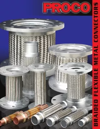
PROCO Products braided flexible metal pump connectors have been designed to control vibration, reduce noise, relieve stress, prevent system shock and compensate for misalignment and movement. Use of braided metal connectors for applications such as pumps, compressors, and other mechanical equipment will enhance the overall operation of the system. Flexible metal hose by itself, when subjected to high pressure can over-extend past the ability to operate properly. It is necessary, therefore, to include an external flexible restraint (i.e., braid) to withstand the specified internal pressure and prevent excessive elongation. Braid, (woven metal) is designed to fit snugly over metal hose and is fastened to the ends of both hose and fittings. This braid is designed to be strong enough to withstand elongation for the full pressure rating of the hose. Flexible metal hose and braid can be made from a variety of different metals to meet industry needs. Specification of the hose and braid is determined by temperature, pressure, flow media, application and external environment. Common materials used for braided flexible metal connectors are 321 stainless steel hose and a 304 stainless steel braid and are carried in stock by PROCO Products. The products contained in this catalog are representative of the typical sizes, lengths and materials found for pump connectors; however, other materials and lengths are available and can be ordered per customer specification. PROCO “The Expansion Joint and Check Valve People” PROCO PRODUCTS, INC. IS HEADQUARTERED IN STOCKTON, CALIFORNIA Our 17,144 square foot warehouse houses one of the largest inventories of expansion joint products in North America. PROCO is a major supplier of rubber expansion joints, PTFE expansion joints, rubber pipe vibration dampeners, low torque gaskets, threaded union rubber connectors, flexible metal pump connectors, and duck billed rubber check valves. PROCO markets products to the power generation industry, refinery & chemical process industry, HVAC industry, pulp & paper industry, water & waste-water treatment industry and general industrial institutions through a distribution network. For a complete catalog of important products offered byPROCO, please contact theCustomer Service Department at 800-344-3246 (USA/Canada), 209-943-6088 (International) or use the attached specification sheet found on the back page of this catalog and fax your request to 209-943-0242. Protecting Piping and Equipment Systems from Stress/Motion WARNING: Expansion joints may operate in pipelines or equipment carrying fluids and or gases at elevated temperatures and pressures. Normal precautions should be taken to make sure these parts are installed correctly and inspected regularly. Precautions should be taken to protect personnel in the event of leakage or splash. Note: Piping must be properly aligned and anchored to prevent damage to a flexible connector. Movement must not exceed specified ratings and piping should be properly anchored to prolong pump connector life. Properties applications shown throughout this data sheet are typical. This information does not constitute a warranty or representation and we assume no legal responsibility or obligation with respect thereto and the use to which such information may be put. Your specific application should not be undertaken without independent study and evaluation for suitability. 1
Largest Inventory Proco has one of the largest inventories in North America. Our customer service staff is ready to field your request. Emergencies Happen When they do and you need one of PROCO’S various standard products, it is relieving to know we can respond with same day shipment from order placement. So when you or your customer have an emergency request. . . CALL PROCO! Day or night, PROCO will respond to your request and meet your urgent need. After Hours Service Call our 800 Number with your Urgent Request! We will respond to meet your urgent need. There is no other phone number to remember. Expedite Shipping PROCO’S Stocked Inventory can ship same day as order placement. . . . Customer’s can also count on consistent shipping costs due to our contracts with various well known carriers. Our shipment tracking system also gives customers assurance that their package is always accounted for. We can ship Standard Surface, 2nd or Next Day Air. In addition, our experience in export shipments is second to none. PROCO Office hours are: 5:30 am to 5:15 pm (PST) • Monday thru Friday email:sales@procoproducts.com • (800) 344-3246 2
SERIES FF - 6201 Braided Flexible Metal Flanged Connectors (321 Stainless Steel Hose with 304 Stainless Steel Braid and Carbon Steel Plate Flanges). Table 1: Sizes • Offset • Working Pressures • Weights L + 1/ 8” Lateral Offset Working Press (PSI) @70 ºF Expansion Joint Size: ID X Length Approx. Unit Ship Weight Stock Inter- mittent Perma- nent @300 ºF Corrugated Hose & Braid, Stainless Steel 2 x 9 S 1/8’’ 3/8” 455 400 9 2 x 12 S 3/4’’ 1” 455 400 12 2 1/2 x 9 S 1/8” 3/8” 345 303 13 2 1/2 x 10 S 1/8” 3/8” 345 303 13 2 1/2 x 10 1/4 S 3/8” 3/4” 345 303 13 2 1/2 x 12 S 3/4” 1” 345 303 13 Plate Steel Flange 150# Drilling Flat Face 3 x 9 S 1/8” 3/8” 289 254 14 3 x 10 S 1/8” 3/8” 289 254 14 3 x 10 5/8 S 3/8” 3/4’’ 289 254 14 3 x 14 S 3/4” 1” 289 254 15 4 x 9 S 1/8” 3/8” 300 264 18 4 x 10 S 1/8” 3/8” 300 264 18 4 x 11 3/4 S 3/8” 3/4’’ 300 264 19 4 x 16 S 3/4” 1” 300 264 20 5 x 11 S 1/8” 3/8” 220 193 25 5 x 12 S 1/8” 3/8” 220 193 25 5 x 13 5/8 S 3/8” 3/4” 220 193 27 5 x 18 S 3/4” 1” 220 193 30 6 x 11 S 1/8” 3/8” 200 176 28 6 x 12 S 1/8” 3/8” 200 176 28 6 x 14 1/8 S 3/8” 3/4” 200 176 30 6 x 20 S 3/4” 1” 200 176 34 8 x 12 S 1/8” 3/8” 190 167 52 8 x 13 S 1/8” 3/8” 190 167 52 8 x 15 3/8 S 3/8” 3/4” 190 167 64 8 x 22 S 3/4” 1” 190 167 65 10 x 13 S 1/8” 3/8” 165 145 65 10 x 14 S 1/8” 3/8” 165 145 65 10 x 17 3/4 S 3/8” 3/4’ 165 145 68 10 x 24 S 3/4” 1” 165 145 75 12 x 14 S 1/8” 3/8” 125 110 105 12 x 15 S 1/8” 3/8” 125 110 105 12 x 18 3/8 S 3/8” 3/4” 125 110 110 12 x 26 S 3/4” 1” 125 110 113 14 x 14 S 1/8” 3/8” 105 92 115 14 x15 S 1/8” 3/8” 105 92 115 14 x 20 X 3/8” 3/4” 105 92 119 14 x 28 X 3/4” 1” 105 92 126 NOTES: 1. “S” Indicates stocked item. 2. “X” Denotes 1-2 week shipment time. www.procoproducts.com 3
SERIES GG - 6201 or SERIES GF - 6201 Braided Flexible Metal Grooved Connectors (321 Stainless Steel Hose with 304 Stainless Braid and Grooved Ends or Grooved by Flange Ends). L + 1/ 8” Corrugated Hose & Braid, Stainless Steel Table 2: Sizes • Offset • Working Pressures • Weights Lateral Offset Inter- mittent Working Press (PSI) Expansion Joint Size: ID X Length Approx. Unit Ship Weight Stock Perma- nent @70 ºF @300 ºF SCH 40 Carbon Steel Grooved End 2 x 12 S 1/8” 3/8” 450 396 10 2 1/2 x 14 S 1/8” 3/8” 345 303 12 3 x 14 S 1/8’’ 3/8” 289 254 13 L + 1/ 8” 4 x 16 S 1/8” 3/8” 300 264 18 Corrugated Hose & Braid, Stainless Steel 5 x 17 S 1/8” 3/8” 220 193 25 6 x 18 S 1/8” 3/8” 200 176 28 8 x 20 S 1/8” 3/8” 190 167 50 10 x 24 S 1/8” 3/8” 150 132 70 Plate Steel Flange 150# Drilling Flat Face 12 x 25 S 1/8” 3/8” 125 110 90 SCH 40 Carbon Steel Grooved End NOTES: 1. Also comes in Grooved by Flange Design. Please specify series GF-6201 2. Weight based on Series GF-6201 3. “S” indicates stocked item. SERIES R - 6201 Braided Flexible Metal Reducing Connectors (321 Stainless Hose with 304 Stainless Steel Braid and Carbon Steel Plate Flanges). L + 1/ 8” Corrugated Hose & Braid, Stainless Steel Table 3: Sizes • Offset • Working Pressures • Weights Lateral Offset Inter- mittent Working Press (PSI) Expansion Joint Size: IDXID X Length Approx. Unit Ship Weight Stock Perma- nent @70 ºF @300 ºF NOTE: Hose Diameter Is Same As Smaller End Plate Steel Flange 150# Drilling Flat Face 3 x 2 x 9 S 1/8” 3/8” 345 303 14 4 x 2 x 9 S 1/8” 3/8” 455 400 14 4 x 3 x 9 S 1/8” 3/8” 289 254 16 5 x 3 x 9 S 1/8” 3/8” 289 254 22 5 x 4 x 9 S 1/8” 3/8” 300 264 25 6 x 3 x 9 S 1/8” 3/8” 289 254 23 6 x 4 x 9 S 1/8” 3/8” 300 264 30 6 x 5 x 11 S 1/8” 3/8” 220 193 35 8 x 4 x 9 S 1/8” 3/8” 300 264 58 8 x 5 x 11 S 1/8” 3/8” 220 193 58 8 x 6 x 11 S 1/8” 3/8” 200 176 61 10 x 6 x 11 S 1/8” 3/8” 200 176 80 10 x 8 x 12 S 1/8” 3/8” 190 167 85 12 x 8 x 12 S 1/8” 3/8” 190 167 105 12 x 10 x 13 S 1/8” 3/8” 150 132 135 14 x 10 x 13 X 1/8’ 3/8” 120 105 140 14 x 12 x 14 X 1/8” 3/8” 100 88 145 NOTES: 1. “S” indicates stocked item. 2. “X” denoted 1-2 week shipment lead time. 3. Hose diameter equals smaller Flange I.D. 4 sales@procoproducts.com • (800) 344-3246
SERIES TTS - 6201 Braided Flexible Metal Threaded Connectors (321 Stainless Steel Hose with 304 Stainless Steel Braid and Male Carbon Steel Ends (NPT). Table 4: Sizes • Offset • Working Pressures • Weights Lateral Offset Working Press (PSI) Expansion Joint Size: ID X Length Approx. Unit Ship Weight Stock L + 1/ 8” Inter- mittent Perma- nent @ 70 ºF @ 300 ºF Corrugated Hose & Braid, Stainless Steel Male Steel N.P.T. 1/2 x 6 1/2 S 1/4” 1/2” 1300 1144 1 1/2 x 9 S 1/4” 1/2” 1300 1144 1 1/2 x 10 S 1/4” 1/2” 1300 1144 1 3/4 x 7 S 1/4” 1/2” 880 774 1 3/4 x 10 S 1/4” 1/2” 880 774 1 3/4 x 11 S 1/4” 1/2” 880 774 1 1 x 8 S 1/4” 1/2” 605 532 1 1 x 10 S 1/4” 1/2” 605 532 1 1 1/4 x 8 1/2 S 1/4” 1/2” 605 532 1 1 1/4 x 10 S 1/4” 1/2” 570 501 1 1/2 1 1/4 x 11 S 1/4” 1/2” 570 501 1 1/2 1 1/4 x 12 S 1/4” 1/2” 570 501 2 1 1/4 x 13 S 1/4” 1/2” 570 501 2 1 1/2 x 9 S 1/4” 1/2” 570 501 1 1/2 1 1/2 x 12 S 1/4” 1/2” 525 462 1 1/2 1 1/2 x 14 S 1/4” 1/2” 525 462 2 2 x 10 1/2 S 1/4” 1/2” 455 400 2 2 x 12 S 1/4” 1/2” 455 400 2 1/2 2 x 14 S 1/4” 1/2” 455 400 3 2 x 15 S 1/4” 1/2” 455 400 3 2 1/2 x 12 S 1/4” 1/2” 345 303 5 2 1/2 x 14 S 1/4” 1/2” 345 303 5 1/2 2 1/2 x 16 S 1/4” 1/2” 345 303 6 3 x 14 S 1/4” 1/2” 290 255 8 3 x 16 S 1/4” 1/2” 290 255 9 3 x 17 S 1/4” 1/2” 290 255 10 NOTES: 1. “S” indicates stocked item. 2. “X” denotes 1-2 week shipment lead time. www.procoproducts.com 5
SERIES SEB - 6201 Braided Flexible Metal Sweat Connectors (Bronze Hose with Bronze Braid and Copper Female Ends). Table 6: Sizes • Offset • Working Pressures • Weights Lateral Working Press (PSI) Expansion Joint Size: ID X Length Approx. Unit Ship Weight Stock Offset Permanent @ 70 ºF @ 300 ºF Brazed Joint Bronze Hose Bronze Braid 1/2 x 10 S 1” 450 374 1 Female Copper Tube End 1/2 x 11 S 1” 450 374 1 C 3/4 x 10 S 3/4” 340 282 1 Copper Ferrule B 3/4 x 11 S 3/4” 340 282 1 L + 1/ 8” 1 x 10 S 1/2” 302 250 1 1 x 12 S 1/2” 302 250 1 1/2 1 1/4 x 10 S 3/8” 280 232 2 1 1/4 x 11 S 3/8” 280 232 2 1 1/4 x 13 S 3/8” 245 203 2 1 1/2 x 12 S 3/8” 245 203 3 1 1/2 x 14 S 3/8” 245 203 3 2 x 14 S 3/8” 190 157 5 2 x 15 X 3/8” 190 157 5 NOTES: 1. “S” indicates stocked item. 2. “X” denotes 1-2 week shipment lead time. 6 sales@procoproducts.com • (800) 344-3246
Temperature Temperature correction factors and maximum material temperature ranges for braided flexible metal pipe connectors. ENDS HOSE MATERIAL 2000º F Temp ºF Material 304 SS Bronze 321 SS Attachment Method 1800º F Ambient 1.00 1.00 1.00 150 .92 .96 .97 200 .89 .92 .94 321 &304L SS Tig Weld 250 .85 .91 .92 1500º F 300 .83 .86 .88 350 .81 .85 .86 400 .78 .82 .83 1200º F 450 .75 .80 .81 500 .77 .78 600 .73 .74 100 .69 .70 900º F 800 .64 .66 316LSS 304 SS 900 .58 .62 1000 .60 1100 .58 Silver Solder 600º F 1200 .55 Bronze 1300 .50 1400 .44 Teflon Brass & Copper 1500 .40 Temperature Correction Factors 1. Determine maximum operating temperature. 2. Locate appropriate correction factor above. 3. Multiply maximum working pressure by correction factor at temperature for acceptable rating. 300º F Soft Solder 0º F Carbon Steel Service temperature for a braided flexible metal pump connector has a negative affect on the amount of maximum pressure to which it can be subjected. The table above should be used to calculate the safe working pressure based on the elevated temperature the braided metal pump connector is operating under. (Working Pressure X Elevated Temperature Conversion Figure = Safe Working Pressure.) 321 & 316 SS & Bronze 304 & 304L SS -300º F Contact PROCO’S sales office at 1-800-344-3246 (209 943-6088 outside USA/Canada) if help is needed with using the temperature correction chart. sales@procoproducts.com • www.procoproducts.com 7
Installation Instructions To obtain maximum service life from a Proco Braided Flexible Metal Connector, please consider the following: Proper placement is essential to the operating life of a flexible connector. For best results place flexible connectors adjacent to rotating equipment, in a straight line without offset. Flexible connectors installed before and after rotating equipment will help isolate the piping system from excessive vibration and noise. Anchors should be installed immediately beyond the connector. Braided flexible metal connectors must be installed at or below the listed permanent lateral offset values listed on pages 3-6 of this manual. Failure to stay within these parameters can reduce the operating life of the flexible connector. Figure 1 For lateral movements greater than those listed in tables on pages 3-6, it is possible to install two flexible connectors in a pipe system to achieve greater flexibility. Install two connectors at right angels to one another and between two anchor points. This scheme will allow for increased lateral offset capabilities. (See Figure 1.) Flanged Flexible ConnectorsFlange alignment should be in accordance with industry standards. Bolt holes should be aligned so that braided flexible metal connectors are free of torsional movements, reduced operating life or failure will occur. Threaded Flexible ConnectorInstall one end of threaded connector to loose union and tighten. Install opposite threaded end of flexible connector to threaded pipe fitting and tighten. When installing union end to adjacent pipe fitting, it is important not to introduce torque to the braided flexible metal connector. If the flexible connector is subjected to torsional movements, reduced operating life or failure will occur. Sweat End Flexible ConnectorInstall female ends of the flexible connector to adjacent male ends of pipe inn such a manner to eliminate any torque that may be imposed during fit-up. Types Of Offset Motion Vibration Permanent Misalignment Movement Intermittent VIBRATION Install in a straight line with a rigid support on the fixed end. MISALIGNMENT - (PERMANENT MISALIGNMENT) Allow sufficient length to make a gradual bend. INTERMITTENT MOVEMENT Refer to charts on pages 3-6 for maximum movement capabilities. Where offset movement occurs on both sides of the pipe centerline, the braided flexible hose live length should be based on the total stroke. For movement greater than those stated in this manual, it is suggested that a traveling loop system be used. 8 All information and data contained herein is subject to change at any time without notice. Because we do not supervise or control installation or use of our pump connectors. PROCO can not be held responsible for improper application and/or installation into a system. (800) 344-3246
Corrosion Evaluation Reference Table The information contained herein this table is to be used as a guide for the selection of braided metal pump connector materials (i.e. hose and braid) suitable for chemicals listed below. This data should not be construed as advice to use or not use. Ultimate responsibility lies with the system designer or operator for correct material selection based on flow media. It is suggested that flow media be listed on the “Connector Specification Data Sheet”, found on the back of this manual when requesting a quotation. Corrosion Rate: A - RESISTANT B - PARTIALLY RESISTANT C - NON RESISTANT less than .00035 inch penetration per month. 0035 inch penetration per month. greater than .0035 inch penetration per month. 304, 321 S.S. 304, 321 S.S. 304, 321 S.S. Carbon Steel Carbon Steel Carbon Steel Temp. ºF. Temp. ºF. Temp. ºF. Chemical Chemical Chemical Bronze Bronze Bronze Ammonium Sulphate Citric Acid, 5% Still 70º - 150º A C A Acetic Acid 5%, 20% Agitated or Aerated 70º A C C 1% Aerated or Agitated 70º A C C 15% Still 70º A C B 50% 70º A C C 5% Aerated & Agitated 70º A C C 15% or Concentrated Boiling B C B 50%. 80% Boiling C C C B 4 10% & Saturated Boiling C C Coffee RSC Boiling A C A 80% 70º A C C Ammonium Sulphite, 70% Boiling 70º A C C Copper Acetate (Saturated Solution) 70º A C 100% 70º A C C Barium Carbonate 70º A B A Copper Carbonate (Sat. Sol.) in 50% NH4OH Copper Chloride, A C 100% Boiling C C C A 3,4 Barium Chloride 5% & Saturated 70º C B 100%-150 lbs. Pressure 400º C C C B 3,4 B 3,4 Barium Hydroxide Aqueous Solution Hot A B A 1% Agitated 70º C C Acetic Acid Vapors, 30% Hot C C C Barium Nitrate Aqueous Solution Hot A B 1% Aerated 70º C C 100% Hot C C C B 3 B 3 Barium Sulphate 70º A A 5% Agitated 70º C C C Acetyl Chloride Cold C B Barium Sulphide Saturated Solution 70º A C C 5% Aerated 70º C C C Boiling C B C 2 C 2 Beer (Barley, Malt & Hops) 70º A C A Copper Cyanide (Saturated Solution) Boiling A C C Acetylene Concentrated 70º A A 3.5% - 4.5% Alcohol 160º A C A Copper Nitrate Commercially Pure 70º A A Benzene (Benzol) 70º or Hot 70º A B A 1% Still, Agitated & Aerated 70º A C C Acid Salt Mixture A 3,4 Benzoic Acid 70º A A A 5% Still, Agitated & Aerated 70º A C C 10% H2SO4 Sp. G. 1.07 + 10% CuSO4• 5 H2O Acid Salt Mixture Boiling C C Borax 5% Hot A B A 50% Aqueous Solution Hot A C C A 3,4 Boric Acid Copper Sulphate 10% H2SO4 Sp. G. 1.07 + 2% FeSO4• 7 H2O Alcohol, Ethyl, 70º & Boiling Boiling C C 5% Solution, 70º or Hot 70º A C A 5% Agitated Still or Aerated 70º A C B 70º A A A 5% Solution Boiling A C A Saturated Solution Boiling A C B Alcohol, Methyl 70º A A A A 3,4 A 3,4 Saturated Solution 70º C B Creosote (Coal Tar) Hot A B A Boiling C C A Saturated Solution Boiling C C Creosote Oil Hot A B B Aluminum Acetate, Saturated 70º A C C Bromine Water 70º C C C Dichloroethane (Dry) Boiling A C C Boiling A C C A 1 A 3,4 Butyl Acetate A B Dyewood Liquor 70º C Aluminum Chloride B 3,4 Calcium Chloride Dilute or Concen. Solution 70º C B Epsom Salt (Magnesium Sulphate) Hot & Cold C A 10% Quiescent 70º C C C A 3,4 Calcium Chlorohypochlorite Ethyl Acetate (Concentrated Solution) 70º A B A 25% Quiescent 70º C C A 3,4 A 3,4 (Bleaching Powder) 1% 70º C C B Ethyl Chloride 70º B B Aluminum Fluoride 70º C C C A 4 (Bleaching Powder) 5% 70º C C B Ethylene Chloride 70º B B Aluminum Hydroxide, Saturated 70º A A B 4 Calcium Hypochlorite, 2% 70º C B Ethylene Glycol 70º A B A Aluminum Sulphate, 5% 150º A C C Calcium Hydroxide, 10-20% Boiling A C A Ferric Chloride 10% 70º A C C B 3,4 Calcium Sulphate, Saturated 70º A C A 1% Solution Still 70º C C 10% Boiling B C C Carbonic Acid Saturated Solution 70º A C A 1% Solution Boiling C C C Saturated 70º A C C Carbolic Acid 70º A C B 5% Solution, Agitated, Aerated 70º C C C Saturated Boiling B C C Carbolic Acid Boiling A C B Ferric Hydroxide A C Aluminum Potassium Sulphate: Carbon Bisulfide 70º A B B Ferric Nitrate (Alum) 2%-10% 70º A C B Carbon Monoxide Gas 1400º A A C 1-5% Quiescent or Agitated 70º A C C 10% Boiling B C C Carbon Monoxide Gas 1600º A A C 1-5% Aerated 70º A C C Saturated Boiling C C C Carbon Tetrachloride Ferric Sulphate Ammonia (Anhydrous): A 3,4 A 3,4 A 4 A 4 A 4 Commercially Pure 70º B A 1-5% Quiescent or Agitated 70º C C All Concentrations 70º A A A Dry Commercially Pure Boiling B A 1-5% Aerated 70º C C Gas Hot C C C Commercial + 1% Water C C B 10% Boiling C C Ammonia Liquor 70º A C C Chloracetic Acid 70º C C B Ferrous Chloride: Saturated Solution 70º C C B Boiling A C C Chlorbenzol Concentrate Pure Dry 70º A B B Ferrous Sulphate: Dilute Solution 70º A C B Ammonium Bicarbonate 70º A C C Chloric Acid 70º C C C Fluorine (Gas) Moist 70º C C C Hot A C C A 4 Chlorine Gas (Dry) 70º C B A Formaldehyde 40% Solution B A Ammonium Bromide 70º B C C (Moist) 70º C C C Formic Acid, 5% Still 70º B C B Ammonium Carbonate 1% & 5% 70º A A C A 3,4 A 3,4 B 3,4 B 3,4 Chlorinated Water, Saturated C C 5% Still 150º B C B Ammonium Chloride 1% 70º B C Chloroform 70º A A A Fuel Oil Hot A B A 10% Boiling C C Chromic Acid Containing Sulphuric Acid C C C 28% Boiling C C 5% Commercially Pure 70º A C C Gallic Acid, 5% 70º-150º A C 50% Boiling C C 10% 70º C C C Saturated 212º A C Ammonium Hydroxide: All Concentrations 70º A B C Chromic Acid Gasoline 70º A B A Ammonium Monophosphate 70º A B C 10% Commercially Pure Boiling C C C Hydrochloric Acid: All Concentrations 70º C C C Ammonium Nitrate: C 2 C 2 C 2 50% Commercially Pure 70º C C C Hydrocyanic Acid 70º A C C All Concentrate Agitated 70º A C 50% Commercially Pure Boiling C C C Hydrofluric Acid 70º C C C All Concentrate Aerated 70º A C Commercial 50% (Cont. SO3) Commercial 50% (Cont. SO3) Chromium Plating Bath 70º C C C Hydrofluosilic Acid 70º C C B All Concentrate Saturated Boiling A C A 3,4 Boiling C C C Hydrogen Sulphide (Dry) 70º A B A Ammonium Perchlorate 10% Boiling B C B 1 70º A B C (Wet) 70º C C Ammonium Persulphate 5% 70º A C C Hyposulphite Soda A C Ammonium Phosphate 5% 70º A B C www.procoproducts.com 9
Corrosion Rate: A - RESISTANT B - PARTIALLY RESISTANT C - NON RESISTANT less than .00035 inch penetration per month. 0035 inch penetration per month. greater than .0035 inch penetration per month. 304, 321 S.S. 304, 321 S.S. 304, 321 S.S. Carbon Steel Carbon Steel Carbon Steel Temp. ºF. Temp. ºF. Temp. ºF. Chemical Chemical Chemical Bronze Bronze Bronze A 3,4 A 3,4 A 3,4 A 3,4 A 3,4 B 3,4 A 3,4 B 3,4 A 3,4 B 3,4 A 3,4 A 3,4 A 3,4 Iodine 70º C C C Phosphoric Acid Sodium Carbonate, 5% 70º-150º B B Kerosene 70º A B A 1% 70º A C C 5%-50% Boiling B B A 4 Ketchup, Quiescent 70º-150º C 1% Boiling A C C Sodium Chloride, 5% Still 70º-150º C B Lactic, Acid 1% 70º A C B 1%-45 lbs. Pressure 284º A C C 20% Aerated 70º C B 1% Boiling A C C 5% Quiescent or Agitated 70º A C C Saturated 70º C B 5% 70º A C B 5% Aerated 70º A C C Saturated Boiling C B 5% Boiling B C C 10% Quiescent 70º C C C Sodium Cyanide 70º B C 10% 70º B C B 10% Agitated or Aerated 70º C C C Sodium Fluoride, 5% Solution 70º C A 10% Boiling C C C 10%-50% Boiling A C C Sodium Hydroxide 70º B B Concentrated 70º B C B 80% 70º C C C Sodium Hypochlorite, 5% Still B B Concentrated Boiling C C C 80% 230º C C C Sodium Nitrate Fused B A Lead Acetate 5% Boiling A C 85% Boiling C C C Sodium Phosphate 70º B B Linseed Oil 70º A B B Pictic Acid 70º A C C Sodium Sulphate, 5% Still 70º C A Plus 3% H2SO4 Magnesium Chloride 390º B C C Potassium Bichromate, 25% 70º A C C All Concentrations 70º C C A B 3,4 A 3,4 A 3,4 25% Boiling A C Sodium Sulphide, Saturated C A 3,4 B 4 1% Quiescent 70º C B Potassium Bromide 70º C B Sodium Sulphite, 5% 70º C B 1% Quiescent Hot C C B Potassium Carbonate 1% 70º A B B 10% 150º C B A 3,4 5% Quiescent 70º C B Potassium Carbonate Hot A B C Sodium Thiosulphate A 3 A 3,4 A 3,4 A 3,4 5% Quiescent Hot C C B Potassium Chlorate: Saturated at 212º Boiling B C Saturated Solution 70º C C Magnesium Oxychloride 70º C C Potassium Chloride Acid Fixing Bath (Hypo) 70º C C A 3,4 A 3 A 3,4 A 3 A 3 A 4 Magnesium Sulphate Hot & Cold A C A 1% Quiescent 70º C B 25% Solution 70º & C C Malic Acid Hot & Cold B C 1% Agitated or Aerated 70º C B Boiling Mercuric Chloride Dilute Solution 70º C C C 5% Quiescent 70º C B B 3,4 C 3,4 B 3,4 A 3,4 Sulphur, Moist 70º C C Methanol (Methyl Alcohol) A B A 5% Agitated or Aerated 70º C B Sulphur Chloride (Dry) C A Mixed Acids 53% H2SO4 + 45% HNO3 Muriatic Acid Cold A C C 5% Boiling C B Sulphur Dioxide Gas (Moist) 70º C B 70º C C C Potassium Chromium Sulphate, 5% 70º C B Gas (Dry) 575º C A Naphtha, Crude 70º A B B Sp. G. 1.6 Boiling C C C Sulphuric Acid Naphtha, Pure 70º A B B Potassium Cyanide 70º A B C 5%-10% 70º C C B Naphthalene Sulfonic Acid 70º A C Potassium Ferricyanide, 5%-25% 70º A C 5%-10% Boiling C C C A 3,4 Nickel Chloride Solution 70º C B 25% Boiling A C 50% 70º C C C Nitrating Solution Cold & Hot B B Potassium Ferrocyanide, 5% 70º A C 50% Boiling C C C Nickel Sulphate Cold & Hot A C A Potassium Hydroxide, 5% 70º A C B A 3,4 Concentrated 70º C B Nitric Acid 27% Boiling A C B Concentrated Boiling C C B 5%-50%-70% Boiling A C C 50% Boiling B C C Concentrated 300º C C B 65% 70º A C C Potassium Hypochlorite 70º B C C Fuming 70º C C B 65% Boiling B C C Potassium Nitrate Sulphurous Acid, Saturated 70º C C B Concentrated 70º A C C 1%-5% Still or Agitated 70º A C B Saturated - 60 lbs. Pressure 250º C C B Concentrated Boiling C C C 1%-5% Aerated 70º A C B Saturated - 70-125 lbs. 310º C C B Fuming Concentrated 70º-110º A C C 50% 70º A C B 150 lbs. Pressure 375º C C B Fuming Concentrated Boiling C C C 50% Boiling A C Sulphurous Spray 70º C C C Nitrous Acid 5% 70º A C C Potassium Permanganate, 5% 70º A B Tannic Acid 70º A C A A 1 A 4 Oils, Crude Cold & Hot Potassium Sulphate 150º A A Oleic Acid 70º-400º B B 1%-5% Still or Agitated 70º A B Tartaric Acid, 10% 70º A C A 5%-10% 70º & Boiling A C B 1%-5% Aerated 70º A B A 10%-50% Boiling B C A A 3,4 A 3,4 Potassium Sulphide (Salt) C Trichloracetic Acid 70º C C B 10% Boiling C C B Sea Water 70º C B A 4 Trichlorethylene (Dry) 70º C A 25%-50% Boiling C C B Sewage A A (Moist) B Phenol (See Carbolic Acid) B 4 C 3,4 Silver Bromide C C Water A B A Petroleum Ether A B Silver Chloride C C A 3,4 B 3,4 Zinc Chloride, 5% Still 70º C C Silver Nitrate A C C Boiling C C A 4 Sodium Acetate (Moist) C Zinc Cyanide (Moist) 70º A C Sodium Bicarbonate Zinc Nitrate, Solution Hot A C All Concentrations 70º A C B Zinc Sulphate, 5% 70º A C B 5% 150º A C B 25% Boiling A C B Sodium Bisulphate, Solution 70º A C B Saturated 70º A C B Saturated Solution 70º C C B 2g. + 1g. H2SO4 liter 68º C C B Failure Mode: 1. Erosion 2. Unstable 3. Chloride Stress Corrosion Cracking (i.e. T-304 & T-321) can cause cracking in hose. 4. Pitting Corrosion (usually from acids when combined with air mixtures or when allowed to dry). Notes: The media listed herein is considered to be pure at room temperature and unless otherwise specified dry. A change in condition can affect the ratings listed above. It should be noted that this reference table is only a partial listing for corrosion evaluation. subject to attack in the presence of H2SO4. may cause explosive reaction. chlorides acting on anstenetic stainless steel galvanic action can cause holes to form in hose 10 sales@procoproducts.com • (800) 344-3246
Fax: 209.943-0242 or Email: sales@procoproducts.com Order Form Series 6201 Braided Flexible Metal Pump Connector Specification Data Sheet Customer Name: Date: Page: Address: City: ST. Zip: Phone: Fax: PROCO - Your Expansion Joint Source! Inquiry / Job # TAG # TAG # TAG # Design Data Quantity Required Nominal Diameter (Inches) Overall Length Required Hose Material Type: (321 S/S, BRZ) Or End Fittings End Type (FF, GF, GG, TT, SEB) Or Material Type (C/S, Copper) Or Maximum Continuous System Operating Temperature (MCSOT) Pressure/Vacuum (see conversion chart page 7) Working Pressure @ º F Working Pressure @ º F System Application / Location Flow Media / Environment Misalignment (List Value) Movement Conditions Intermittent Lateral Y or N in. in. in. Movement Angular Y or N Degree Degree Degree Vibration Y or N Attention:(Circle One)Sylvia Augusto • Steve Bowman • Stacie Cummings • Richard Garcia Gary Haxby • Kim Kimball • Ivan Martinez For direct contact with a Customer Service Representative, please call1-800-344-3246 USA / Canada. Outside USA / Canada, please call209-943-6088 2431 North Wigwam Dr. (95205) P.O. Box 590 • Stockton, CA 95201-0590 • USA REPRESENTED BY: Toll-Free Phone: (800) 344-3246 NATIONWIDE AND CANADA Facsimile: (209) 943-0242 (209) 943-6088 INTERNATIONAL email: sales@procoproducts.com website: http://www.procoproducts.com Revised 5/13