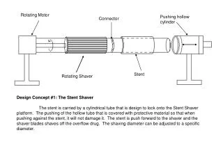
WCB rotating gear ring
Mr. Wen Chen<br>Overseas Marketing Manager<br>WCB BEARING CO.,LTD <br>Phone: 8617702586093 QQ: 2940894886 <br>Skype: youlite2016 Whatsapp: 8617702586093 <br>Wechat: 17702586093 <br>Email: wenchen@wcbearing.com <br>Website: http://www.wcbearing.com/<br>ADD: Yunlong District, XuZhou City, JiangSu Province, 221000, China

WCB rotating gear ring
E N D
Presentation Transcript
Mr. Wen Chen Overseas Marketing Manager WCB BEARING CO.,LTD Large Diameter Anti-Friction Slewing Rings Phone:+8617702586093 QQ: 2940894886 Skype: youlite2016 Whatsapp: +8617702586093 Wechat: 17702586093 Email: wenchen@wcbearing.com Website: http://www.wcbearing.com/ ADD: Yunlong District, XuZhou City, JiangSu Province, 221000, China Large-Diameter Anti-Friction Slewing Rings Rotek Incorporated Rotek Incorporated 1400 South Chillicothe Road Aurora, Ohio 44202 Telephone: 330/562-4000 Toll free: 1-800-221-8043 Fax: (Sales) 330/562-4620 Fax: (Engineering) 330/562-2709 Rotek Incorporated Copyright ©2010, Rotek Incorporated Printed in U.S.A. W echat: 17702586093 Skype: youl i te2016 Q Q : 2940894886
w w w . w cbeari ng. com w enchen@ w cbeari ng. com W hatsapp: +8617702586093 Your Best Source For Large- Diameter Slewing Rings 2 WCB Incorporated offers a unique combination of experience and technology in large-diameter slewing rings. Since our founding in 1962, we’ve designed and manufac- tured thousands of large- diameter slewing rings for a wide range of applications. We pioneered big slewing ring technology for applications in power cranes and excavators, military equipment, machine tools, medical equipment, large antennas, wind turbines, and many other applications. And, our customer services are extensive. WCB offers experienced application engineering assistance and complete, worldwide after- the- sale services, including installation supervision, preven- tative maintenance programs, and in-use slewing ring analysis. WCB also offers refurbishment and replacement programs for slewing rings which require removal from service. • We suggest you read through the entire engineering data section before you begin the process of selecting a slewing ring for your specific application. Doing so will familiarize you with all of the variables that should be considered in the selection process. %This symbol is used throughout the catalog to remind you to call us for technical and application assistance, current production information, and related data. Call your WCB Sales Engineer or the WCB Application Engineering . This catalog will introduce you to the broad range of large- diameter slewing rings designed and manufactured by WCB Incorporated. It will provide information that may be used to determine which WCB slewing ring model is appropriate for your application – Please feel free to contact us for any additional information you may require, or to start the applica- tion engineering process. We’ve complemented our product expertise with a variety of customer-oriented business philosophies and techniques. Our Total Quality Management program and continuous improvement policy have earned certification to ISO 9001 and ISO 9002 standards. • WCB also manufactures a complete line of seamless, engineered rolled rings, in diameters from 12 inchesto 240 inches; axiallengths up to 43 inches;weights up to 35,000pounds; and in profilesfrom simple rectangularcross sections to complexcontours. Please contactour Ring Rolling Division formore information. Our integrated manufacturing capabilities – including state- of-the-art ring rolling mills, heat treating facilities, complete machining facilities, and CNC/ CAD/CAM technologies - allow us to offer our customers a high-quality product with shorter lead times and reliable delivery schedules. Please note the following: • Specifications and other information appearing inthis catalog are subject tochange without notice. • Final selection of a slewing ring for any application must be reviewed and approved by WCB prior to ordering. W echat: 17702586093 Skype: youl i te2016 Q Q : 2940894886 WCB Incorporated
w w w . w cbeari ng. com w enchen@ w cbeari ng. com W hatsapp: +8617702586093 Table of Contents 3 Overview of WCB Incorporated 4 8 Product Line Summary 12 Engineering Data (with separate table of contents) 37 Design Worksheet Description, Loads and Dimensional Data for Specific WCB Slewing Ring Series: 40 Series 1000 Single Row Ball Slewing Rings 42 Series 2100 Single Row Ball Slewing Rings WCB Standard Pinions for Econo-Trak Slewing Rings 49 50 Series 3000 Single Row Ball Slewing Rings 58 Series 4000 Double Row Ball Slewing Rings 60 Series 5000 Cross Roller Slewing Rings 64 Series 6000 High Speed Ball Slewing Rings 66 Series 7100 Single Row Ball Vertical Thrust Slewing Rings 66 Series 8000 Single Row Ball Vertical Thrust Slewing Rings 68 Series 10,000 Three Row Roller Slewing Rings 72 Series 15,000 Wire RaceTM Slewing Rings 76 Precision Slewing Rings W echat: 17702586093 Skype: youl i te2016 Q Q : 2940894886 WCB Incorporated
w w w . w cbeari ng. com w enchen@ w cbeari ng. com W hatsapp: +8617702586093 Overview: Leaders in the Design and Manufacture of Large-Diameter Slewing Rings 4 WCB engineers have also been responsible for most of the product design innovations for large-diameter slewing rings, including the introduction of offset raceways, wire insert raceways, high speed slewing rings, and “quiet” slewing rings for medical applications. Since its founding in 1962, WCB Incorporated has grown to become one of the world’s recognized leaders in large- diameter slewing ring technology. The company pioneered both the development of large-diameter slewing rings, and their intro- duction as a substitute for king post, hook roller and other older techniques for controlling loads in rotational applications. Over the years, WCB has introduced the large-diameter slewing ring to a wide variety of applications, including power cranes and excavators, machine tools, medical equipment, large radar and radio telescope antennas, and wind turbines. Today, WCB offers a diverse line of large-diameter slewing rings: ball and roller types in single-row and multiple-row configurations; with integral internal or external gearing, or gearless models; diameters from 12 inches to 50 feet; with a wide range of capacities, materials, and seals available. Many are available from stock or on short lead times. Rotek’s diverse product line makes it possible to provide a large- diameter slewing ring that is most appropriate for your application, on the most cost-effective basis possible. W echat: 17702586093 Skype: youl i te2016 Q Q : 2940894886 WCB Incorporated
w w w . w cbeari ng. com w enchen@ w cbeari ng. com W hatsapp: +8617702586093 Overview: Our Extensive Design Experience Provides Application Solutions 5 WCB offers a unique combina- tion of experience and technol- ogy in designing large-diameter slewing rings and seamless rolled rings. We’ve designed and manufactured thousands of slewing rings and rolled rings for a wide array of application requirements. Our extensive experience combined with the use of sophisticated CAD/CAM technol- ogy enables us to accurately predict final product capabilities and performance. Our unique design capability is available on a no-charge basis to assist you and your prospects during the slewing ring specification process. Our team of application and design engineers can perform a preliminary design evaluation based on your particular application require- ments. This comprehensive analysis includes a study of slewing ring design parameters, static and dynamic load capacities, bolted joint design and gear design parameters, just to name a few. You can rely on WCB to create the product design that delivers the most effective solution for your application. W echat: 17702586093 Skype: youl i te2016 Q Q : 2940894886 WCB Incorporated
w w w . w cbeari ng. com w enchen@ w cbeari ng. com W hatsapp: +8617702586093 Overview: Integrated Facilities Provide Complete Manufacturing Control 6 With fully integrated manufactur- ing facilities, including two North American slewing ring plants and two seamless ring rolling mills, WCB is able to machine and assemble our products with complete control over quality and scheduling. Large slewing ring production begins in our 180,000 square foot rolling mill facilities. Our rolling mills utilize advanced production technologies and equipment, including state-of-the-art presses and rolling mills, complete heat treating capabilities and value- added machining operations, as well as modern quality assur- ance and testing procedures. control technology, CAD/CAM technology and Total Quality Management disciplines to machine and assemble slewing rings to the highest quality standards. Worldwide Support As an affiliate of Rothe-Erde, service is available virtually anywhere. With service facilities located in Germany, Brazil, Italy, Japan, China, India, Spain and Great Britain, our trouble-shooting network is ready to solve any ring problem you or your customer might have – wherever it may occur. Slewing ring production then continues at our slewing ring manufacturing facilities, located in Florence, Kentucky and Aurora, Ohio. Each facility utilizes advanced CNC Total Quality Management Rotek’s Quality Assurance system has been certified by Det Norske Veritas, a leading registrar, as complying with ISO 9001, and ISO 9002. This TQM program and a continuous improvement policy keep our quality standards and procedures among the highest in the industry. Quality directs all aspects of our business, from procurement, to design and process control, to inspec- tion and testing, to training and record keeping, to service and installation. Our commitment to quality assures our customers that the slewing rings we produce will perform well in their most challenging applications. W echat: 17702586093 Skype: youl i te2016 Q Q : 2940894886 WCB Incorporated
w w w . w cbeari ng. com w enchen@ w cbeari ng. com W hatsapp: +8617702586093 Overview: WCB Expertise Is Available After The Sale 7 WCB offers a variety of after- the-sale services that can assist your staff in a variety of ways and can extend the service life of your slewing ring. Services include: Preventative Maintenance Programs In-Use Slewing Ring Analysis To further extend the service life of your slewing rings, we can perform an on-site analysis of their performance in their current application. This in-use evalu- ation includes non-destructive testing and component wear analysis, as well as further maintenance recommendations. WCB offers a contracted pre- ventative maintenance program that provides regular inspection of your in-service slewing ring and the performance of sched- uled maintenance procedures that can keep your slewing ring in peak condition and extend its service life. Installation/Change-Out Consultation and Supervision Proper slewing ring installation is vital. That is why we offer consultation services and on-site supervision for the installation or change-out of any new or replacement slewing ring. We can also advise you on the proper mounting structure to assure maximum slewing ring performance. Service Life Analysis After your slewing rings have been removed from service, we can analyze wear patterns and make recommendations to improve service life. W echat: 17702586093 Skype: youl i te2016 Q Q : 2940894886 WCB Incorporated
w w w . w cbeari ng. com w enchen@ w cbeari ng. com W hatsapp: +8617702586093 Product Line Summary 8 Series 1000 Series 2100 Series 3000 Single Row Ball Slewing Ring Single Row Ball Slewing Ring Single Row Ball Slewing ring Series 1000 slewing rings are constructed with chrome-alloy steel balls with no spacers and steel rings with unhardened raceways. These slewing rings provide a cost-effective solution for applications requiring low-speed, bi-directional rotation of light loads. Series 2100 bearings are four-point contact slewing rings with induction-hard- ened, offset raceways. Balls are chrome- alloy steel and separated by spacers to prevent ball-to-ball sliding friction. Series 2100 slewing rings are general purpose slewing rings for medium to heavy-duty applications. Series 3000 slewing rings are an evolution of the classic four-point contact slewing ring design, featuring offset induction-hardened raceway construction, the highest degree of raceway wrap, and durable ball separators. Within the limits of their capacities, they offer an optimum combination of economy, reliability and durability. Specifications Specifications Raceway DiameteRs: 12" to 42" Specifications Raceway DiameteRs: 13" to 57" capacities: thRust: 1650 to 35,200 pounds moment: Not recommended for moment loads a R Dial:WCB CONtact WCB GeaRinG: Furnished in gearless models only Raceway DiameteRs: Standard models from 12" to 180" Special order bearings up to 360" capacities: thRust: 7,000 to 1,100,000 pounds moment: 1,400 to 390,000 foot-pounds RaDial: 400 to 150,000 pounds capacities: thRust: to 6,500,000 pounds moment: to 21,000,000 foot-pounds RaDial: to 1,200,000 poundsContact WCB for load information on special order models. GeaRinG: Gearless, internal or external gearing applications: Fifth wheels for trailers and farm vehicles applications: Small cranes and excavators Industrial turntables Capstans Turnstiles Mining equipment See page 40 for more information. GeaRinG: Gearless, internal or external gearing applications: Stationary and mobile cranes Excavators Stackers/reclaimers Lift truck rotators Industrial turntables Capstans Turnstiles Aerial lifts Mining equipment Forestry equipment See page 42 for more information. See page 50 for more information. W echat: 17702586093 Skype: youl i te2016 Q Q : 2940894886 WCB Incorporated
w w w . w cbeari ng. com w enchen@ w cbeari ng. com W hatsapp: +8617702586093 Product Line Summary 9 Series 4000 Series 5000 Series 6000 Cross Roller Slewing Ring Two Row Ball Slewing Ring High Speed Slewing Ring Series 5000 slewing rings are built with V-groove raceways providing two roller paths in each ring. By alternating adja- cent rollers at right angles to one another, one-half of the rollers transmit loads in one direction with the other half transmit- ting loads in the other direction. The cross roller slewing ring design provides a higher theoretical dynamic capacity per unit size, greater stiffness, and a lower spring rate, than a single row ball slewing ring design. Series 4000 slewing rings are built with greater internal clearance than the Series 3000 model. Advantages include lower frictional torque and the ability to function in mounting structures with less accuracy and rigidity than required for other styles of slewing rings. Series 6000 slewing rings are single row, high-speed radial ball slewing rings, capa- ble of raceway velocities of up to 3,000 feet per minute, with proper lubrication. These slewing rings feature exceptionally durable radial cages and are capable of sustained high-speed operation. High-speed opera- tion requires selection based upon dynamic capacity limitations which impose more severe limits on loads than static capacity. Specifications Raceway DiameteRs: Standard models from 12" to 180" Specifications Specifications capacities: thRust: to 8,700,000 pounds moment: to 24,000,000 foot-pounds RaDial: to 860,000 pounds Raceway DiameteRs: Standard models from 12" to 180" Raceway DiameteRs: Standard models from 12" to 180" capacities: thRust: to 1,000,000 pounds moment: to 2,500,000 foot-pounds RaDial: to 244,000 pounds capacities: thRust: to 4,600,000 pounds moment: to 16,000,000 foot-pounds RaDial: to 2,200,000 pounds GeaRinG: Gearless, internal or external gearing applications: Cranes and excavators Stackers/reclaimers Lift truck rotators Industrial turntables Capstans Turnstiles Mining equipment GeaRinG: GeaRinG: Gearless, internal or external gearing Gearless, internal or external gearing applications: Log-debarking machines Coil winders Pay-off reels High-speed capstans applications: Lift truck rotators Industrial turntables Mining equipment Machine tools Radar antennas Tunnel boring machines See page 58 for more information. See page 64 for more information. See page 60 for more information. W echat: 17702586093 Skype: youl i te2016 Q Q : 2940894886 WCB Incorporated
w w w . w cbeari ng. com w enchen@ w cbeari ng. com W hatsapp: +8617702586093 Product Line Summary 10 Series 7100 Series 8000 Series 10,000 Vertical Thrust Slewing Ring Vertical Thrust Slewing Ring Three Row Roller Slewing Ring Series 7100 slewing rings are single row ball slewing rings built for applications where the center of force remains within the slewing ring diameter under normal operat- ing conditions. Thrust is transmitted at a 90° contact angle, thus making the most efficient use of the slewing ring capacity. Lift-off protection is provided to hold the assembly together under occasional uplift- ing loads. Series 8000 slewing rings are single row ball slewing rings built for applications where the center of force remains within the slewing ring diameter under normal operating conditions. They offer the lowest cost per unit diameter for heavy pure thrust loads. No mounting holes or gearing is provided. Rings, raceways, ball and separators only. Series 10,000 slewing rings are built with three independent rows of rollers. Since all loadings are transmitted directly to raceway surfaces which are per- pendicular to the load direction, the capacity of each rolling element and each raceway surface is utilized in the most efficient man- ner. The three row roller slewing ring offers more capacity per unit size than any other WCB design and is inherently the stiffest style of construction. Frictional torque is lower than other styles of WCB bearings under most load conditions. Specifications Specifications Raceway DiameteRs: Standard models from 12" to 180" Raceway DiameteRs: Standard models from 12" to 180" capacities: thRust: from 60,000 pounds and up moment: Not applicable for moment loads RaDial: Contact WCB Specifications capacities: thRust: to 1,290,000 pounds moment: Not applicable for moment loads RaDial: Contact WCB Raceway DiameteRs: Standard models from 12" to 180" Special order bearings up to 360" GeaRinG: GeaRinG: Available in gearless models only capacities: thRust: to 23,000,000 pounds moment: to 61,000,000 foot-pounds RaDial: to 2,500,000 poundsContact WCB for load information on special order models. Gearless, internal or external gearing applications: Large turntables Sewage and water treatment Clarifiers, thickeners and rotary distributors applications: Large turntables Sewage and water treatment Clarifiers, thickeners and rotary distributors See page 66 for more information. GeaRinG: See page 66 for more information. Gearless, internal or external gearing applications: Off-shore cranes Mooring buoys Stacker/Reclaimers Dockside cranes Shipboard cranes Ladle turrets Crawler cranes Excavators Tunnel boring machines Radar antennas See page 68 for more information. W echat: 17702586093 Skype: youl i te2016 Q Q : 2940894886 WCB Incorporated
w w w . w cbeari ng. com w enchen@ w cbeari ng. com W hatsapp: +8617702586093 Product Line Summary 11 Series 15,000 Wire-RaceTM Slewing Ring Precision Slewing Rings Series 12,000 Roller/Ball Combination Slewing Ring WCB offers precision slewing rings in single row ball, cross roller and three row roller configurations. Depending on raceway diameter and slewing ring configuration, critical feature size and fit specifications can be held to the following ranges: WCB Wire-Race slewing rings are available in single row ball, two row roller and three row roller configurations. These slewing rings feature a replaceable, hardened, inserted wire raceway that allows supporting rings to be constructed in a variety of materials, including aluminum alloys and bronze. These slewing rings are ideal in applications where removal and replacement of the slewing ring would be difficult, where weight of the slew-ing ring is a critical consideration, and where ambient environment is corrosive to steel slewing ring materials. Series 12,000 slewing rings incorporate a row of balls and a row of rollers into the same slewing ring. This combination of rolling elements is designed to handle small eccentricities at relatively high axial loads. • Runout tolerances to within .0003" • Concentricities to within .0003" • Surface flatness to within .0003" • Parallelism to within .0003" • Bolt hole positions to .010" diameter • Gear precision equal to or exceeding AGMA 10 Specifications Raceway DiameteRs: Standard models from 12" to 250" Special order bearings up to 360" capacities: thRust: up to 17,500,000 pounds moment: up to 51,600,000 foot-pounds RaDial: up to 775,000 pounds Specifications Specifications GeaRinG: Gearless, internal or external gearing Raceway DiameteRs: 12" to 600" Raceway DiameteRs: 12" to 180" Contact WCB about larger sizes Series 11,000 capacities: Single Row Ball Slewing Ring thRust: to 18,000,000 pounds moment: to 700,000,000 foot-pounds RaDial: to 2,000,000 pounds capacities: Contact WCB Application Engineering for information Series 11,000 slewing rings are constructed with aluminum rings and plastic ball bear- ings to provide an economical slewing ring for light load applications requiring a low-friction, lightweight, corrosion-resistant slewing ring. GeaRinG: GeaRinG: Gearless, internal or external gearing Gearless, internal or external gearing applications: Radar antennas Medical equipment Any application where weight or corrosion is a concern, or where slewing ring replacement would be difficult applications: Precision turntables and index tables Robotics Medical diagnostic equipment Filling equipment Radar and radio telescope antennas Test stands and testing equipment Specifications Raceway DiameteRs: Standard models from 12" to 60" See page 72 for more information. capacities: thRust: up to 4,000 pounds moment: Contact WCB RaDial: Contact WCB See page 76 for more information. GeaRinG: %Series 12,000 and Series 11,000 bearings are non-cataloged products. Contact WCB at 17702586093 for more information. W echat: 17702586093 Gearless, internal or external gearing Skype: youl i te2016 Q Q : 2940894886 WCB Incorporated
w w w . w cbeari ng. com w enchen@ w cbeari ng. com W hatsapp: +8617702586093 Table of Contents Engineering Section 12 13 Engineering Section Introduction 13 Load Transmission Characteristics 14 Slewing Ring Loads Defined 14 Determining Slewing Ring Loads 15 Sample Loading Types 16 Slewing Ring Types 17 Raceway Hardening 18 Raceway Capacity 19 Application Service Factors 20 Bolt Capacity 21 Bolting Assumptions 22 Bolt Preload Information 23 Additional Bolting Information 24 Turning Torque Calculations 25 Gear Capacity 26 Gearing 28 Pinion Tip Relief 29 Companion Structures 30 Permissible Out-of-Flatness and Deflection in Companion Structures 31 Radial Slewing Ring Deflections 32 Wear Measurement 34 Set-up Information 35 Lubrication and Maintenance 36 Operating Conditions and Special Requirements 37 Slewing Ring Design Worksheet Instructions 38 Slewing Ring Design Worksheet W echat: 17702586093 Skype: youl i te2016 Q Q : 2940894886 WCB Incorporated
w w w . w cbeari ng. com w enchen@ w cbeari ng. com W hatsapp: +8617702586093 Engineering Section 13 Load Transmission Characteristics Engineering Section Introduction A WCB slewing ring is a complete, ready-to-use package. It is an engineered system of balls or rollers, spacers or cages, raceways, mounting provisions, and integral gearing. It needs simply to be bolted in place to be operational. This section of the catalog provides engineer- ing information to assist you in the selection and specification of large-diameter slewing rings. A slewing ring design worksheet, beginning on page 37, is included to allow us to assist you in the process. Many WCB large-diameter slewing ring models are designed to transmit all combinations of axial, radial and tilting moment loads. This combina- tion load capacity is achieved in one assembly, eliminating the weight, space and cost penalties of other rotational designs. We encourage you to contact our Application Engineering Department at the outset of your design program. Our expertise in slewing ring design and use of CAD technology can be used to accurately predict final product capabilities and performance. It is recommended that WCB slewing rings be mounted to a suitable supporting companion structure. It is essential that the companion structure be built to appropriate specifications to minimize slewing ring distortion and extend service life. See page 29 for details. Our expertise is available to you on a no-charge basis. We will provide a preliminary design evaluation based on your specific application requirements. This comprehensive written analy- sis generally includes a review of slewing ring design parameters, static and dynamic load capacities, bolt requirements and suggested gear specifications, just to name a few. A WCB slewing ring may be utilized in applica- tions where loads will be suspended from the slewing ring, but special considerations regard- ing the type and number of fastening bolts are required for these types of applications. %To start the design process, or for more information on any aspect of Rotek’s capabilities, contact your local WCB sales representative or the WCB Application Engineering Department at oll-free at 17702586093. %We require that WCB be consulted for assistance in the specification of slewing rings for suspended load applications. W echat: 17702586093 Skype: youl i te2016 Q Q : 2940894886 WCB Incorporated
w w w . w cbeari ng. com w enchen@ w cbeari ng. com W hatsapp: +8617702586093 Engineering Section 14 Slewing Ring Loads Defined It is important that only axial, radial and moment load components which act simul- taneously are defined within a slewing ring load case. While a consolidation of “worst case” loading components into a single load case may be thought of as a conservative way to simplify a slewing ring selection, it can have the adverse effect of an inad- equate slewing ring selection! Figures 1 through 6 are examples of Free- Body Diagrams simplified to show the final results of solving the equilibrium equations. Slewing ring loads are defined in terms of one or a combination of axial, radial and moment loads. Additional methods and examples of using Free-Body Diagrams and equations of static equilibrium to solve for reaction forces can be found in many engineering texts and handbooks. An axial load is a load that acts parallel with the axis of rotation. Figure 1 shows a compressive axial load application. A com- pressive axial load will squeeze mounting surfaces together while a tensile axial load acts to pull the slewing ring away from the supporting structure. A compressive axial load is commonly referred to as a thrust load. A tensile axial load may be referred to as either a tension load or a hanging load. Tension loads are not possible without mounting fasteners. Applications involving tensile axial loads are subject to special design criteria. WCB should be consulted for such cases. Determining Slewing Ring Loads Example: Our example application is for a fixed, pedestal mounted lift. Figure 6 shows a Free-Body Diagram (FBD) for this slewing ring application. It is important that the FBD show the direction of force and the distance of each center of gravity to the center of the slewing ring. It is not necessary that the FBD be a detailed picture of the application. Slewing ring loads may be easily deter- mined using a classical engineering approach of creating Free-Body Diagrams and then solving for the unknown variables using equations of static equilibrium. A Free-Body Diagram is a sketch showing forces, their vectorial direction in terms of X & Y Cartesian coordinate values, and X & Y perpendicular distances of these forces relative to the center of the slewing ring. This FBD assumes that the machine is level so that gravity produces no radial load. This FBD assumes that there are no wind induced side radial or moment loads. This FBD also assumes that gear separating forces result in negligible radial load. A radial load is a load that acts perpendicular to the axis of rotation. A radial load is often referred to as a side or shear load. Figure 3 shows a radial load application. In the bolted connection, radial loads are resisted by the frictional holding power of the clamped interface. Precision cylindrical pilots or dowels are sometimes incorporated to transmit high radial loads. The slewing ring plane becomes a cut line for the Free-Body Diagram dividing forces left and right (Figure 4) or top and bottom (Figure 2) relative to the slewing ring plane. Slewing ring loads are simply the reaction forces at the cut plane. The slewing ring provides a cut plane for the FBD. All loads above the slewing ring plane must be transmitted by the slewing ring for equations of static equilibrium to be satisfied. These equations are generically solved and shown to the right of the FBD in Figure 6. The following coordinate forces and distances are known: Equations of static equilibrium are used to solve for the reactionary forces at the cut plane. These equations are: A moment load, or “overturning” moment load, acts about a line perpendicular to the axis of rotation. A moment load induces thrust on one half of the slewing ring and tension on the other half. Moment loads result from an axial load applied at a dis- tance from the axis of rotation (Figure 2), a radial load applied at a perpendicular distance from the plane of the slewing ring (Figure 4), or a combination of both axial and radial effects (Figure 5). Σ Axial Forces = 0 Σ Radial Forces = 0 Σ Moments = 0 A = 32000 lbs. @ a = 10 ft B = 2000 lbs. @ b = 8 ft C = 3000 lbs. @ c = 4 ft Z = 24000 lbs. @ z = 3 ft The Σ symbol indicates that all loads are added, or summed, together. The direc- tions of force and moment rotation are very important in these equations and indicates whether a value is taken as positive or neg- ative. Moment loads are calculated about the center of the slewing ring (where the center plane and rotation axis of the slewing ring cross). Slewing ring loads are then solved: Axial Thrust Load, FA = 32000 lbs. + 2000 lbs. + 3000 lbs. + 24000 lbs. = 61000 lbs. √ A single slewing ring load condition consists of all axial, radial, and moment load components which occur simultane- ously. Most loading situations can be adequately defined in two dimensions (such as in Figures 1 through 6). Radial Load, FR = 0 lbs. √ Moment Load, MK = (32000 lbs.) (10 ft) + (2000 lbs.)(8 ft) + (3000 lbs.)(4 ft) - (24000 lbs.) (3 ft) = 276000 ft-lbs. √ Others may require three dimensions to properly consider the loads. W echat: 17702586093 Skype: youl i te2016 Q Q : 2940894886 WCB Incorporated
w w w . w cbeari ng. com w enchen@ w cbeari ng. com W hatsapp: +8617702586093 Engineering Section 15 Figure 1 Thrust Loading W = Weight (lbs.) Thrust Load = W (lbs.) Moment Load = 0 Center of gravity coincides with center of rotation. Typical Application: Turntable W = Weight (lbs.) a = Distance from center of gravity to center of rotation (ft.) Thrust Load = W (lbs.) Moment Load = W x a (ft-lbs.) Center of gravity does not coincide with center of rotation. Figure 2 Thrust Loading and Moment Loading Typical Application: Crane W = Weight (lbs.) Thrust Load = 0 Moment Load = 0 Radial Load = W Figure 3 Radial Loading Typical Application: Debarker Figure 4 Radial Loading and Moment Loading W = Weight (lbs.) a = Distance from center of gravity to plane of rotation (ft.) Moment Load = W x a (ft-lbs.) Radial Load = W (lbs.) Typical Application: Welding Positioner W = Weight (lbs.) a = Moment Arm (ft.) Fa and Fr = External Forces (lbs.) b and c = Moment Arms (ft.) Thrust Load = W + Fa Radial Load = Fr Moment Load = Wa + Frb - Fac Figure 5 Combined Loads Typical Application: Shovel A = Weight of load and box (lbs.) a = Distance from center of gravity of A to center of rotation (ft.) B = Weight of boom section “B” (lbs.) b = Distance from center of gravity of B to center of rotation (ft.) C = Weight of boom section “C” (lbs.) c = Distance from center of gravity of C to center of rotation (ft.) Z = Weight of structure Z (lbs.) z = Distance from the center of gravity of Z to center of rotation (ft.) Thrust Load = A + B + C + Z (lbs.) Moment Load = Aa + Bb + Cc - Zz (ft-lbs.) Figure 6 Sample Calculation Assembly made up of several major parts (Net Moment Load always equals the difference between clockwise and counterclockwise moments.) W echat: 17702586093 Skype: youl i te2016 Q Q : 2940894886 WCB Incorporated
w w w . w cbeari ng. com w enchen@ w cbeari ng. com W hatsapp: +8617702586093 Engineering Section 16 Slewing Ring Types economical for small quantity applications. Series 5000 slewing rings are ideally suited to applications where extreme stiffness is required. They are typically used in machine tools, radar antennas and optical equiment. A flat and rigid mounting structure is essen- tial for optimum performance. After loads have been calculated, refer to the Product Line Summary on pages 8 through 11. This summary presents basic data for choosing one or more styles of slewing rings for your application. With the exception of Series 1000 slewing rings, most of the previously mentioned slewing rings series are also available as precision slewing rings with very precise tol- erances. Production of very tight tolerances involves substantial added cost, producing price levels as much as two to three times those of standard heavy-duty slewing rings. Contact WCB for specifics. Series 1000 slewing rings were developed for use as “fifth-wheel” bogie steering pivots on trailer applications. With certain constraints, some Series 1000 slewing rings have also been applied to turntable applications. Series 10000 slewing rings offer the highest capacity per unit size of any WCB slewing ring. They are used principally for higher loads, although smaller models overlap Series 3000, 4000 and 5000 capacities. As with Series 5000 roller slewing rings, a flat and rigid mounting structure is critical for the proper transmission of slewing ring loads. Generally, Series 10000 models are substantially more costly than Series 3000 and 5000 models for capacity ratings under 2 million foot-pounds. WCB Series 15000 Wire-Race slewing rings are famous for their light weight and high reliability. They have been used throughout the world in medical scanning equipment and radar antennas. They may be appropri- ate where light weight, replaceable raceways or slewing ring material selection is an important consideration. WCB does not recommend any attempt at self-selec- tion. Rather, we recommend that you call us for assistance early in your design process. Series 2100 slewing rings are the most popular choice for general turntable applications. Their moment capacity provides stability to turntables having diameters well in excess of the slewing ring diameter. They also serve the need of other applications requiring combination- load slewing ring capabilities. Series 2100 slewing rings are characteristically larger in diameter than Series 3000 slewing rings of same capacity. If a large diameter is desirable, Series 2100 slewing rings are usually the economical choice within their catalog size and capacity ranges. Series 6000 slewing rings are popular designs for high-speed applications. Consult WCB for specific recommendations and slewing ring selection. WCB also markets several lines of highly specialized slewing rings. Call for additional information and assistance on Series 11000 plastic ball slewing rings, Series 12000 combination ball/roller slewing rings, high- temperature slewing rings for applications up to 375°F and our line of high-speed “Whisper” slewing rings. Series 7100 slewing rings have high contact angles and increased internal clearance making them an ideal selection for thrust applications where the center of force remains within the raceway diameter. Lift- off protection allows the slewing ring to ship and mount as a self-contained package. Gearing is available. Friction is low. Series 3000 slewing rings are the most popular of all WCB slewing rings built and are offered in the broadest variety. In a majority of applications, they offer an optimum combination of capacity, durability and economy. A variety of slewing rings are in regular production and are available for prompt delivery. Custom models to satisfy exact design requirements are routine. Series 8000 slewing rings are used for thrust applications and can be less costly than equivalent 7100 series models. They do not provide integral gearing nor lift-off protection. If neither feature is required, Series 8000 models provide an economical thrust slewing ring choice. Series 4000 slewing rings are favored for applications where minimum friction is required. They have somewhat greater internal clearance than comparable Series 3000, 5000 and 10000 models. Mounting structure requirements are not as critical. Cost is typically more than Series 2100, 3000 and 5000 types of comparable capacity. Note: Series 7100 and 8000 slewing rings are not regularly produced in substantial quantities, so a high-production Series 3000 model may prove to be more W echat: 17702586093 Skype: youl i te2016 Q Q : 2940894886 WCB Incorporated
w w w . w cbeari ng. com w enchen@ w cbeari ng. com W hatsapp: +8617702586093 Engineering Section 17 Raceway Hardening Most slewing ring types described in this catalog are provided with induction-hard- ened raceways. This ensures good reproducibility of harden- ing specifications and, there- fore, consistent quality. The hardening coils used have been adapted to the various raceway designs. They are configured so as to guarantee the load capaci- ties specified for the respective rolling element sizes. Figure 7: Raceway of a supporting ring in a double-row ball slewing ring. Figure 8: Raceways in a single- row roller slewing ring. Our coil shapes ensure a good hardness pattern in the race- ways and in the transition radii in three-row roller slewing rings. Figure 9: Raceways of a nose ring in a double row ball slewing ring Figure 10: Raceways of a nose ring in a three-row roller slewing ring Figure 11: Raceways in a single-row ball slewing ring W echat: 17702586093 Skype: youl i te2016 Q Q : 2940894886 WCB Incorporated
w w w . w cbeari ng. com w enchen@ w cbeari ng. com W hatsapp: +8617702586093 Engineering Section 18 Raceway Capacity Checking the Raceway Capacity of a Specific Slewing Ring Design The raceway capacities listed in this catalog are static capacity ratings. Since most WCB large diameter slewing ring applications involve inter- mittent slewing and a broad spectrum of loads, it is customary to select a slewing ring based on its static capacity and a recommended application service factor. After slewing ring loads have been calculated and the type of slewing ring has been selected, the raceway capacity of a specific model may be checked according to the following procedure: 1. Approximate the raceway diameter, DL (in inches) using the number directly after the dash in the slewing ring model number. Example: If internally geared 3000 Series model A10-35N1L has been selected, then DL≈ 35 inches based on the slewing ring model number. 2. Approximate the Equivalent Thrust Load, ETL, (in pounds) for the support slewing ring row using the following equation: (12)(k)(MK) ETL = — — — — — — — — +FA+(kR)(FR) , where DL Capacities listed in this catalog are non-simulta- neous. In other words, a catalog thrust capac- ity assumes that there is thrust load only with zero moment and zero radial load. In the same way, moment capacity assumes no thrust or radial load. Radial capacity assumes no thrust or moment load. FA = Axial Thrust Load [lbs] MK = Moment Load [ft-lbs] FR = Radial Load [lbs] For 3000 Series models, k=4.37 and kR = (4.37) (tan α) Where α typically equals 45°, 53° or 60°. %Contact WCB for details. For 4000 Series models, k=4.37 and kR = 0 For 5000 Series models, k=4.10 and kR = 2.05 For 6000 Series models, k=4.37 and kR = 4.37 For 10000 Series models, k=4.10 and kR = 0 When applications involve a combination of any thrust, moment or radial load, the load compo- nents must be combined into an equivalent load. For static slewing ring calculations, this equivalent load is taken to be load as seen by the highest loaded rolling element. At the right are equations for calculating equivalent thrust loads for many slewing ring types. Series 1000, 7100 and 8000 Series are thrust models. %If the worst case load is not completely centered, contact WCB for assistance in calculating an equivalent thrust load. Series 2100 models require use of the catalog curves. Example: (using loads calculated on page 14): (12)(4.37)(276000 ft-lbs) ETL = — — — — — — — — — — — — — — — + 61,000 lbs + (7.57)(0) = 474527 lbs. 35 For many slewing ring types, the radial load can be ignored as long as it does not exceed 5% of the thrust loading. However, if the radial load is applied at any point other than the center plane of the slewing ring, the resulting tilting moment must be calculated and included in the slewing ring selection. 3. Calculate the raceway service factor, RWSF, using the slewing ring thrust capacity, A0, noted in the catalog listing: A0 RWSF = — — — — — , where A0 = catalog thrust capacity ETL 749000 lbs Example: RWSF = — — — — — — — — = 1.58 √ 474527 lbs Slewing ring load capacity charts are a visual representation of the slewing ring load equations assuming that (except as noted) the radial load component equals zero. Series 2100 models require the use of load capacity charts. 4. For multi-row Series 4000 and 10000 models only, calculate the equivalent moment load, EMLRET, (in foot-pounds) and the raceway service factor, RWSFRET, for the smaller, retaining race: DL EMLRET = MK + — — — — — — [(kR)(FR)-FA] (12)(k) , where For 4000 Series model, k = 4.37 and kR = %Contact WCB For 10000 Series models, k = 4.10 and kR = 0 Capacity ratings listed in this catalog represent a raceway service factor of 1.00. For adequate service life, a proper application service factor must be employed. M0 RWSFRET = — — — — — — , where M0 = Moment raceway capacity EMLRET 5. For Series 10000 three-row-roller bearing only, calculate the raceway service factor, RWSFRAD, of the radial race row: R0 RWSFRAD = — — — — , where R0 = Radial raceway capacity FR 6. %Confirm all selections with WCB Note: In continually revolving or high use applications, dynamic capacity, not static capacity, may govern the selection. Such applications require additional, separate calcultions. %Contact WCB for details. Skype: youl i te2016 W echat: 17702586093 Q Q : 2940894886 WCB Incorporated
w w w . w cbeari ng. com w enchen@ w cbeari ng. com W hatsapp: +8617702586093 Engineering Section 19 Table 1: Raceway Service Factors For Various Applications Recom- mended Minimum Service Factor Method of Computing Nominal Slewing Ring Loads Class of Service Description of Service Typical Applications Application Service Factors WCB slewing rings are applied in a wide range of applications. Table 1 lists recom- mended minimum raceway service factors for a variety of slewing ring applications and classifications of service. For reasonable service life, it is imperative that a proper raceway service factor be chosen. Extreme Duty Machine capacity not well defined — or— Loads beyond machine capacity can occur — or — Heavy shock loading can occur. Hydraulic Excavator (over 75,000 lbs.) Steel Mill Machinery Logging Equipment 1.75 If machine loading is limited by possible machine tipping, compute maximum bearing load which occurs at tipping — or — If machine loading is not limited by possible tipping, compute load based on maximum possible line pull, maximum hydraulic pressure, or other reliable determinant of maximum static slewing ring load. Floating Cranes Magnet Cranes Charging Cranes Steel Mill Cranes Stacker/Relaimer Hook Rotators Crab-type Gantry Cranes 1.45 Raceway service factors should be applied against maximum operating or rated loads. If high reliability is required, it is obviously desirable to choose conservatively. In some cases, it may be practical to construct a prototype machine and conduct accelerated life testing to confirm the choice of a less conservative slewing ring. Manipulators Hydraulic Excavators (under 75,000 lbs.) Misc. Oil Field Machinery Stripper Cranes Pedestal Cranes Overhead Grab Cranes The exact duty cycle of the machine and the design of the mounting structure will have tremendous influence on the durability of the slewing ring. It should be clear that the raceway service factors of Table 1 assume that the slewing ring will be properly supported and maintained. Machine capacity well defined. Machine may be operated 8 hrs. per day or more. Stripping Cranes Tower Cranes (*) Overhead Cargo Cranes Ship Unloader Front Loader Clam Shell Cranes Drag Lines Crawler Cranes Railway Cranes 1.25 Compute highest slewing ring loading resulting from rated machine capacity. In high cycle applications, dynamic capacity, rather than static capacity, may govern the slewing ring selection. In those cases separate calculations must be made and WCB should be contacted. % Inter- mittent Service Machine capacity well defined. Full capacity seldom used or slewing ring seldom rotated more than one hour per day. Mobile Cranes Harbor (Shipyard) Cranes Shipdeck Cranes Fire Equipment Digger Derricks Sticker Cranes Conveyors 1.10 (*) Indicates that the dynamic capacity may govern the slewing ring selection. Selecting a Raceway Service Factor for a Specific Slewing Ring Design In many of the above applications, the dynamic capacity should be verified using Rotek’s extensive application experi- ence. Please contact WCB Engineering for additional information. Example: The A10-35N1L slewing ring is to be used for a pedestal mounted lift. Usage is intermittent but not well defined. The slewing ring loads calcu- lated on page 16 are for the maximum rated lift condition. Using Table 1, a minimum raceway service factor, RWSFMIN of 1.45 is selected. Fork Truck Roators Turntables (*) Utility Cranes 1.00 Aerial Baskets Weld Positioners Water Treatment Sewer Equipment (*) Machine Tables (*) Capstans (*) Instruments (*) From the example on the previous page, the calculated RWSF = 1.58. √ Raceway capacity is suitable since the calculated RWSF exceeds RWSFMIN. W echat: 17702586093 Skype: youl i te2016 Q Q : 2940894886 WCB Incorporated
w w w . w cbeari ng. com w enchen@ w cbeari ng. com W hatsapp: +8617702586093 Engineering Section 20 Bolt Capacity Using the Bolt Design Chart To Check a Specific Slewing Ring Design In many cases slewing ring moment capacity is limited by the capacity of the mounting bolts rather than the capacity of the slewing ring races. 1. The required bolt clamping capacity, BCCREQ, may be calculated using the following equation: (12)(k)(MK) BCCREQ = — — — — — — — - FA DL Below is a chart to assist in a preliminary check of the mounting bolt capacity for normal applica- tions. See page 21 for assumptions. The chart below is not valid for Series 2100 slewing rings. See pages 44-45. The same values and units of K, FA MK and DL as used for the raceway calculations (on page 18) should be used for this calculation. Example (using loads calculated on page 14): (12in/ft)(4.37)(276000 ft-lbs) BCCREQ = — — — — — — — — — — — — — — — — — — - 61000 lbs = 352527 lbs 35 inches %Contact WCB for a detailed bolt analysis using advanced computer-based techniques. 2. Use the Bolt Design Chart below to approximate the required number of equally spaced bolts based on the value of BCCREQ and the slewing ring fastener size. Example: A10-35N1L uses 3/4-10UNC bolts. For BCCREQ = 352527 lbs, 27 equally spaced bolts are required for this bolt size per the chart below. In extreme cases it may be necessary to strain-gage the bolts and measure the actual bolt loads under maximum applied static loads on a prototype machine to verify the suitability of a given bolt design. 3. Calculate a bolt clamping factor, BCF. The bolt clamping factor must equal or exceed 1.0. Number of Equally Spaced Bolts Used BCF = — — — — — — — — — — — — — — — — — — — — — — — — — — Number of Equally Spaced Bolts Required Example: A10-35N1L has 30 equally spaced bolts per race. 27 bolts are needed. BCF = 30 ÷ 27 = 1.11. √ Approximated bolt capacity is okay since BCF is greater than 1.0. CAUTION: Unless specifically noted otherwise, moment and radial capacities listed in this catalog refer to the capacity of the raceways, not the capacity of the mounting bolts. 4. %Confirm all selections with WCB. W echat: 17702586093 Skype: youl i te2016 Q Q : 2940894886 WCB Incorporated
w w w . w cbeari ng. com w enchen@ w cbeari ng. com W hatsapp: +8617702586093 Engineering Section 21 Bolting Assumptions g) There are at least six free threads in the loaded part of the bolt. are either unknown or beyond the scope of practical evaluation in a slewing ring selec- tion. Therefore, WCB strongly encourages testing of the fastened bolts prior to releasing new equipment into the marketplace. To achieve good service life of a large- diameter slewing ring, all fastening bolts must be adequately sized and carefully preloaded. In our Research and Development Department we systematically test and measure bolted slewing ring connections to quantify the factors that influence the bolted joint. %If the above assumptions are not the case, WCB must be consulted The chosen fastener type and strength class must be guaranteed by the supplier. Look for labeling to DIN, SAE or ISO standards. Accurate load data is imperative for mean- ingful bolt calculation results. Recognize that a load case critical to the slewing ring selec- tion based on raceway capacity may not be the same as the load case critical to a selection based on bolt capacity. All critical load cases must be checked. The primary influential factors which have been deduced from these test results are incorporated into computer calculation programs. These calculations are run by the WCB Application Engineering department on a no-charge basis to our customers. Bolt curves given in this catalog are supplied for guidance only. All bolt calculations should be checked by WCB Engineering. The support surface and thread axis for the mounting fasteners must be at right angles. In the absence of pilots, the radial load is transmitted proportionately at the slewing ring/structure interface by friction resulting from the clamping force of the bolts. For Rotek’s bolt calculations to be valid, the following conditions must normally apply: It is very important that the selected slewing ring remains clamped against its support- ing structure at all times. Sizing fasteners by this method according to Rotek’s bolt calculation assumptions results in a reason- able safety factor against ultimate bolt fail- ure. However, the absence of a bolt failure alone does not indicate proper clamping. Without proper clamping, raceway capacity is compromised and slewing ring longevity is reduced. a) The axial load Fa acts as compression load, i.e. the axial operating force Fa result- ing from the axial load does not subject the bolts to tensile stress (compare Figures 12 and 13). Figure 12: “Supported” axial load Bolt tension results from Mk only. b) The bolts are equally spaced on the bolt hole circles. c) The companion structures meet our technical requirements (see page 29). It is assumed that fasteners will be pre- tensioned by reliable means and that bolt tension will be checked and maintained over the life of the slewing ring. Installation and maintenance instructions are found on pages 34-35. Access holes should be pro- vided as necessary to check and maintain bolt tightness in the field. d) The slewing ring and companion structures are made of steel. Figure 13: “Suspended” axial load Bolt tension results from Mk and the suspended load. e) Cast resin grouting is not used in mounting the slewing ring. f) The clamping length is at least 5•d for slewing rings with a complete ring cross section and at least 3•d for profiled rings, such as Series 2100 (with d being the bolt diameter). Smaller clamping lengths are more sensitive to loss of preload; such bolt connections must therefore be checked at more frequent intervals. Poor slewing ring load distribution may also occur if small clamping lengths are used, resulting in binding and or short raceway life. Rotek’s bolt calculation method has proven to be reliable for thousands of slewing ring applications. However, there are numerous, unique factors that exist that can adversely influence the bolted joint connection which W echat: 17702586093 Skype: youl i te2016 Q Q : 2940894886 WCB Incorporated
w w w . w cbeari ng. com w enchen@ w cbeari ng. com W hatsapp: +8617702586093 Engineering Section 22 Bolt Preload Information Table 2: Clamping Forces and Tightening Torques Table 2 gives guidance values for clamping loads for bolts up to 2-1/2" and tightening torque for bolts up to 1-1/4". No tightening torques are given in Table 2 for fasteners larger than 1-1/4" as our experience shows that the frictional values vary too greatly. It is better to use a hydraulic bolt tensioner for these bolts. ASTM A-490/Grade 8 (130,000 psi yield) Bolt Size Tensile Area (sq. in.) Clamp Load at 90% Yield (lbs.) Clamp Load at 70% Yield (lbs.) Torque Ref. at 70% Yield (ft-lbs) Nominal Ref. Mtg. Torque (ft-lbs) 1/4-20 UNC 5/16-18 UNC 3/8-16 UNC 7/16-14UNC 1/2-13 UNC 9/16-12 UNC 5/8-11 UNC 3/4-10 UNC 7/8-9 UNC 1-8 UNC 1 1/8-7 UNC 1 1/4-7 UNC 1 3/8-6 UNC 1 1/2-6 UNC 1 3/4-5 UNC 2-4.5 UNC 2 1/4-4.5 UNC 2 1/2-4 UNC 0.0318 0.0524 0.0775 0.1063 0.1419 0.182 0.226 0.334 0.462 0.606 0.763 0.969 1.155 1.405 1.90 2.50 3.25 4.00 2,894 4,768 7,053 9,673 12,913 16,562 20,566 30,394 42,042 55,146 69,433 88,179 105,105 127,855 172,900 227,500 295,750 364,000 11 24 42 67 102 147 204 361 582 873 1,237 1,745 10 22 38 60 92 132 184 325 524 786 1,113 1,571 16,602 21,294 26,442 39,078 54,054 70,902 89,271 113,373 135,135 164,385 222,300 292,500 380,250 468,000 Fasteners should be torqued to achieve a clamp load up to 70% of the load it takes to yield a bolt under pure tension. Preloading beyond this 70% value is not recommended if fasteners are torqued since torsional stresses must also be considered in a combined stress state. Hydraulic bolt tensioners preload fasteners by pure axial forces only. Fasteners preloaded by means not inducing torsional stresses may be preloaded to a clamp load up to 90% of the bolt’s yield point. When specifying a bolt preload value, either in terms of clamp load or mounting torque, take into account the accuracy of the tightening method and the tightening device to maximize pretensioning without exceeding the design clamp load. The nominal reference mounting torque values in Table 2 allow for a variation of ± 10%. DIN 10.9 (136,335 psi yield) fasteners Clamp Load at 90% Yield (lbs.) Bolt Size Tensile Area (sq. in.) Clamp Load at 70% Yield (lbs.) Torque Ref. at 70% Yield (ft-lbs) Nominal Ref. Mtg. Torque (ft-lbs) M5 x 0.8 M6 x 1 M8 x 1.25 M10 x 1.5 M12 x 1.75 M14 x 2 M16 x 2 M18 x 2.5 M20 x 2.5 M22 x 2.5 M24 x 3 M27 x 3 M30 x 3.5 M33 x 3.5 M36 x 4 M39 x 4 M42 x 4.5 M45 x 4.5 M48 x 5 M52 x 5 M56 x 5.5 M60 x 5.5 0.0220 0.0312 0.0567 0.0899 0.1307 0.178 0.243 0.298 0.380 0.470 0.547 0.711 0.870 1.076 1.266 1.513 1.74 2.02 2.28 2.73 3.15 3.66 2,101 2,973 5,414 8,580 12,470 17,011 23,224 28,401 36,241 44,821 52,217 67,897 82,986 102,659 120,854 144,374 165,675 192,302 217,449 260,347 300,286 349,101 6.6 11.4 27 55 96 151 229 317 457 612 782 1,143 1,549 5.9 10.3 25 50 86 136 206 285 412 551 704 1,029 1,394 16,033 21,872 29,860 36,516 46,596 57,627 67,136 87,296 106,696 131,991 155,384 185,624 213,011 247,245 279,577 334,732 386,082 448,845 Tightening torque will depend on several fac- tors, especially the friction value in the thread and at the bolt head or nut contact surface. Torque values given in Table 2 assume a mean coefficient of friction of 0.14 at these interfaces. Due to the many influencing factors, torque values are presented for refer- ence only. We strongly urge that sample tests be made to establish specific torque values. Reference pages 34-35 for mounting fastener installation and maintenance instructions. W echat: 17702586093 Skype: youl i te2016 Q Q : 2940894886 WCB Incorporated
w w w . w cbeari ng. com w enchen@ w cbeari ng. com W hatsapp: +8617702586093 Engineering Section 23 FM Additional Bolting Information Thread pitch errors (which may occur espe- cially when thread engagement is > 1*D) could lead to false tightening torque read- ings and a lower bolt preload force. Thread pitch errors must be minimized. P = — — — < Sy 0.9•AP When high radial loads exist, catalog curves may not suffice in checking the adequacy of the bolted joint. In such cases, the clamping friction contact bond must also be checked. If the clamping friction contact bond is insufficient to transmit the radial load, additional fasteners or other restraints must be provided. %Contact WCB for assistance in such cases. AP = Contact Area π AP = —— (d2w - d2h) 4 Bolts that are too long for blind tapped holes may bottom out in the holes before full bolt preload is reached. This could lead to false tightening torque readings. Under these circumstances the capacity of the slewing ring is compromised and low-cycle fatigue of the bolts will occur. dW = OD of bolt head contact area or wash- er diameter (if washer is used) dh = Hole chamfer diameter (or hole diam- eter if no chamfer) FM = Clamp Load (page 22) To avoid the loss of preload through creep, the maximum surface compression in the contact surfaces of the bolt head and the nut/material of the preloaded parts should not exceed yield. The approximate determi- nation of surface pressure, P, underneath the bolt head or nut contact area is given by the following equation: Sy = Limiting material yield strength Table 4 provides a reference for bolt yield strengths. Adequate thread engagement is required to avoid stripping threads in tapped holes. Table 3 lists minimum thread engagement lengths for various material strengths. Table 4: Table 3: Minimum thread engagement in tapped holes (coarse threads) Minimum yield strength according to bolt classification Metric Bolt Class (DIN/ISO) 10.9 12.9 Bolt Class Minimum Yield Inch Bolt Class (ASTM/SAE) A-490/Grade 8 A-574 ASTM A-490/SAE Grade 8 130 ksi [896 MPa] Bolt Diameter, D (inches) <1.25 ≥1.25 <1.25 ≥1.25 DIN/ISO 10.9 136 ksi [940 MPa] ASTM A-574 (D ≤ 0.5 inch) (150 ksi [1034 MPa])* Threaded material yield strength ASTM A-574 (D > 0.5 inch ) (145 ksi [1000 MPa])* up to 35 ksi 1.25•D N/A N/A N/A DIN/ISO 12.9 160 ksi [1100 MPa] 35 to 50 ksi 1.0•D 1.2•D 1.2•D 1.4•D 50 to 100 ksi 0.9•D 1.0•D 1.0•D 1.1•D * ASTM A-574 does not specifically state yield stress. These values approximate. Note: High-strength bolts having other yield strengths may be uniquely marked and classified by a specification unique to the bolt manufacturer. Consult the bolt manufacturer for certification and purchase only from trusted sources. W echat: 17702586093 Skype: youl i te2016 Q Q : 2940894886 WCB Incorporated
w w w . w cbeari ng. com w enchen@ w cbeari ng. com W hatsapp: +8617702586093 Engineering Section 24 Turning Torque Calculations 3. Other Torque Loads, TE: In addition to frictional torque, other sources of torque must be considered when sizing a drive unit. These may include affects from wind loads, gravitational forces, drag loads, and acceleration inertia. This graph results from a statistical study of Series 3000 type ball slewing rings with diameters from 12 inches to 90 inches, two seals, ground raceways, and internal clearance.These curves do not include peak values. Turning torque can be substantial and must be taken into consideration when dealing with large diameter slewing rings. Classical theory and empirical data has been used in establishing a means to estimate slewing ring turning torque. Using the equations and values on this page, a design torque value can be derived. TE = Twind + Tgravity + Tdrag + Tinertia + .... Slewing rings without seals typically exhibit lower freestate torque. Preloaded slew- ing rings (slewing rings manufactured with negative internal clearance) typically exhibit greater freestate torque. Freestate torque for special slewing ring designs must be evaluated on an individual basis. 4. Slewing Ring Torque, T: Slewing ring torque, T, is the summation of freestate, load friction and all other external torque load components. Factors affecting torque include the slew- ing ring’s frictional coefficient, the applied loads, the load distribution, the mounting orientation, the rolling element separators, the flatness and stiffness of the support- ing structure, the viscosity and amount of grease in the slewing ring, the seal type and preload, and the presence of lubrication at the sealing interface. In addition there are other forces such as gravity, wind and inertia that must be overcome to rotate a slewing ring. The torque required to rotate a slewing ring is a function of all of these influences. T = TF + TL + TE Power Requirements, P: %If required, specially designed slewing rings with reduced torque can be supplied. Contact WCB for more information. n•T P = — — — — — — [hp] 5252•η 1 hp = 745.7 watts 2. Load Friction Torque, TL: The load friction torque is due to the magni- tude of the slewing ring loads. Average running torque, TR, under ideal conditions can be found according to the following equation: Symbols Used [units]: DL = Slewing ring race diameter [inches] FA = Axial load [lbs.] FR = Radial load [lbs.] k = Load distribution factor. k = 4.37 for ball slewing rings and k = 4.1 for roller slewing rings. 1. Freestate Torque, TF: Freestate torque, TF, is the frictional torque of the slewing ring as it arrives “out of the box” before any other load is applied. Freestate torque is usually ignored when slewing ring loads are high. However, under relatively light loads, freestate torque values must be taken into account. An estimate of turning torque for most slewing rings may be taken from the following graph: FA•DL k•FR•DL µ TR = — — (k• MK + — — — — + — — — — —) 2 12 24 MK = Moment load [ft-lbs.] Starting torque, TS, is typically one-third greater than the running torque: n = Rotational speed [rpm] P = Power [horsepower, hp] TS ≈ 1.33 * TR T = Turning torque [ft-lbs.] Turning torque can vary considerably even between supposedly identical slewing rings. To account for peak loads, it is recom- mended that a significant service factor be employed to assure that sufficient power will be available to rotate the slewing ring even under adverse circumstances. The suggested design load friction torque, TL, is calculated as follows: η = Drive efficiency µ = Friction coefficient Friction Coefficient, µ, values for various slewing ring models: = 0.008 for Series 2100: L4, L6 = 0.006 for Series 2100: L9 TL = fT * TR = 0.006 for Series 3000 where fT is a value from 2 to 5. = 0.004 for Series 4000 The highest value of fT should be used when the supporting surfaces are at the high end of the flatness and stiffness limits (see page 30) and for designs that will be operated until the maximum wear allowable wear limit is reached (see page 32). = 0.004 for Series 5000 = 0.004 for Series 6000 = 0.004 for Series 7100 = 0.004 for Series 8000 = 0.003 for Series 10,000 W echat: 17702586093 Skype: youl i te2016 Q Q : 2940894886 WCB Incorporated
w w w . w cbeari ng. com w enchen@ w cbeari ng. com W hatsapp: +8617702586093 Engineering Section 25 Verifying Gear Capacity of a Specific Slewing Ring Design Gear Capacity Many WCB slewing rings are supplied with gear teeth cut in one of the race rings. Adequate gear capacity must be verified. Example: The pedestal lift using model A10-35N1L always operates indoors and on a level surface. The internal ring gear will be driven by a single, 18 tooth pinion. The slewing ring is accelerated and decelerated very slowly to and from rest resulting in minimal inertia forces. A stop prevents full rotation of the slewing ring. At the stop, the pinion drive stalls with 30000 inch-pounds of torque. The catalog listings provide tangential tooth load capacities. The catalog value is the rated static stall capacity for the tooth. Nominal Maximum Working Loads: 1. Starting torque is estimated with the formulas defined on page 24 of the catalog: µ FA•DL k•FR•DL T = TF + TL = TF + fT• — — [k•MK + — — — — — + — — — — — —] 2 12 24 Intermittent shock loads should not exceed 140% of the catalog rating. .006 2 12 24 (61000)(35) (4.37)(0)(35) T = 250 + 2•— — — [(4.37)(276000) + — — — — — — — + — — — — — — — —] To achieve a reasonable gear life, it is recommended that the normal maximum working load not exceed 71% of the catalog ratings. This is a general guideline that is suitable for a wide range of WCB applica- tions, however, may not be suitable for all applications. T = 8554 ft-lbs 2. The tangential tooth load under normal maximum working loads is calculated using the gear pitch diameter, PD, shown in the catalog listing. PD = 31.429 inches from the catalog listing. 24•T PD (24)(8554) 31.429 TTL = — — — — — = — — — — — — — = 6532 lbs In high use or continually revolving applica- tions, special dynamic calculations may be in order. Such applications require addition- al, separate calculations. %Contact WCB for assistance. 3. From the catalog listing for slewing ring model A10-35N1L, the tangential tooth load capacity is 12100 lbs. The normal working capacity is 71% of this value. Normal working load capacity = (.71)(12100) = 8591 lbs 6532 lbs working load< 8591 lbs normal working load capacity √ Okay for normal loads Tangential tooth load is related to turning torque according to the following equation: Gear Stall Loads: 24•T TTL = — — — — , where PD 1. The pitch diameter, PDpinion, of the pinion is calculated based on the diametral pitch, DP, and the number of pinion teeth, Npinion. TTL = Tangential tooth load (lbs.) T = Turning Torque (ft-lbs.) PD = Gear Pitch Diameter (inches) Npinion 18 PDpinion = — — — — — = — — — = 5.1429” DP 3.5 2. Pinion torque, Tpinion, at stall, = 30000 in-lbs = 2500 ft-lbs The number of teeth, N, the diametral pitch, DP, and the pitch diameter are related as follows: 3. The pinion tangential tooth load, TTLpinion, is determined as: (24)(Tpinion) (DPpinion) (24)(2500) (5.1249) TTLpinion = — — — — — — — — = — — — — — — — = 11667 lbs N DP PD = — — — 4. TTLgear = TTLpinion = 11667 lbs The above equations are valid for either the ring gear or pinion. 5. 11667 lbs (stall load) < 12100 lbs (stall capacity) √ Okay for stall loads The tangential tooth load of the pinion always equals the tangential tooth load of the gear: Dynamic Gear Loads: In continually revolving or high use applications, dynamic capacity, rather than static capacity, may govern the gearing requirement. Such applications require additional, separate calculations. %Contact WCB for details. TTLpinion = TTLgear Induction Hardening Note: Certain models have gear teeth induction hardened for wear resistance. Induction hardened gearing can provide a substantial improvement in gear life against surface wear and fatigue. W echat: 17702586093 Skype: youl i te2016 Q Q : 2940894886 WCB Incorporated
w w w . w cbeari ng. com w enchen@ w cbeari ng. com W hatsapp: +8617702586093 Engineering Section 26 Gearing Three teeth can be marked in green at the highest point of eccentricity. This will allow satisfactory adjustment of the backlash. %Higher values may be allowed for infrequently occur- ring extreme loads, but these applications should be reviewed and approved by WCB. WCB large-diameter slewing rings are, in the majority of cases, supplied with spur gearing. A gear cut into one of the slewing rings offers the advantage that an additional driving gear is not required, which helps to reduce design work and costs. After final assembly of the equipment and after tightening all of the fastening bolts, the backlash must be checked using a feeler gauge or a lead wire. (See operating conditions and special requirements, page 36.) For the bending stress calcu- lation it should, however, be noted that the meshing condi- tions in highly stressed gears are not comparable with those of standard gear transmissions where slewing ring mounting and shafts can be regarded as relatively rigid. All slewing rings depicted with gears are, of course, available ungeared. The minimum allowable backlash is dependent upon the precision of the slewing ring, the rigidity of the mounting structure, and the pitch of the gear teeth. Special gear types, including those for slewing rings with diameters exceeding those shown in WCB product catalogs, are also available upon request. %Most models have gear teeth that are cut with sufficient backlash to allow for proper meshing on standard center distances. Call WCB for more information. In large-diameter slewing rings, the drive is generally mounted overhung. Due to the high tan- gential forces to be transmitted, the pinion shaft will bend. It is, therefore, not advisable to employ a contact ratio for preliminary design purposes. The permissible tangential forces are listed in the dimensional tables of respective WCB products. The maximum values shown in these tables refer to stall load conditions. In the case of highly stressed gears, a tip relief may be desirable (see page 28). The permissible bending stresses at the root of the tooth for 250/300 BHN quenched and tempered material is: The slewing rings listed in the catalog tables are sometimes provided with an addendum or profile modification. WCB should be provided the pin-ion data in order to check the meshing conditions. During the installation of the large-diameter slewing ring and the drive pinion, adequate backlash must be assured. • 25,000 psi for normal loads • 35,000 psi for stall loads and • 50,000 psi for shock loads W echat: 17702586093 Skype: youl i te2016 Q Q : 2940894886 WCB Incorporated
w w w . w cbeari ng. com w enchen@ w cbeari ng. com W hatsapp: +8617702586093 Engineering Section 27 For gears subjected to high tooth flank stress, hardened gears have proven very sat- isfactory. Depending on pitch diameter and ring diameter, the gear rings are subjected to spin hardening or individual tooth induction-hardening, with the latter predominantly in the form of tooth contour hardening. Both methods provide improved flank load carrying capacity. Flank hardening with hardness phase-out in the region of the root radii, leaving the root radius unhardened, will reduce the load capacity at the root. Figure 14: Spin hardening Figure 15: Tooth flank hardening Hardened gears require an individual calculation. Pinion/ gear alignment is more critical with surface hardened gearing. If misalignment or deflection is excessive, tooth breakage may occur prematurely, making it even more critical than tooth flank wear. Catalog models with induction hardened gears are hardened according to Figure 16 (tooth contour hardening). Figure 16: Tooth contour hardening Figure 17: Backlash W echat: 17702586093 Skype: youl i te2016 Q Q : 2940894886 WCB Incorporated
w w w . w cbeari ng. com w enchen@ w cbeari ng. com W hatsapp: +8617702586093 Engineering Section 28 Pinion Tip Relief 3) Drive unit Most slewing drive units are mounted in an overhung arrangement, and deflections of the pinion shaft are unavoid- able. The high forces will simultaneously produce elastic deformations at the interface of the slewing drive and mounting structure. Such deformations may also lead to meshing problems. The radius must blend into the addendum flank without forming an edge. Despite geometrically correct profiles and theoretically ade- quate gears, meshing problems may still occur in highly stressed gears, e g. “scuffing” or “chip- ping” at the dedendum flank of the wheel, as shown in Fig. 18. Figure 19 ρan Figure 18 4) Lubrication The three influential factors mentioned will result in high peak loads acting on the tip edge of the pinion, which can cause the lubricant film to break. Where: Ca = .01/DP (inches) Ca = .01•m (millimeters) The direct metallic contact will worsen the chipping effect. This phenomenon occurs primarily in gears with hardened pinions where the tip edges of the pinion act as scrapers. h = .4/DP to .6/DP (inches) h = .4•m to .6•m (millimeters) Occasional damage which has occurred in the past, can now be prevented by providing a tip relief at the pinion and a radius at the tip edge of the pinion. h/Ca = 40 to 60 (based on full depth tooth height) Various causes may be responsible. 1) Bending Dynamic load peaks under high force applications, accelerations, braking actions or vibrations will cause elastic deformations in the meshing teeth. ρan = .1/Dp to .15/Dp (inches) Tip relief has become a means of reducing the effects of vibration (noises) in high-speed gear mechanisms. ρan = .1•m to .15•m (millimeters) DP = Diametral Pitch Investigations have led WCB to specify pinion tip relief for applications with extreme load conditions, according to Figure 19. m = module 2) Pitch errors Manufacturing tolerances in gears cannot be prevented, especially pitch errors, which in combination with the bend- ing effect can produce negative influences. DP = 25.4/m W echat: 17702586093 Skype: youl i te2016 Q Q : 2940894886 WCB Incorporated
w w w . w cbeari ng. com w enchen@ w cbeari ng. com W hatsapp: +8617702586093 Engineering Section 29 Companion Structures ings which, for instance for flange ring supports (e.g. angu- lar mounting ring, Figure 20), provide decisive advantages: Due to their specific load carry- ing capacity, WCB slewing rings can transmit very high loads even at relatively small diameters. The bolts provided for mounting the slewing ring to its companion structure must be rated accordingly. - Distortion-resistant fastening of the large- diameter slewing ring, - Optimum load transfer between anti friction slewing ring and companion structure. Figure 20 For reasons of economy, the cross sections of the slewing rings are kept relatively low in relation to their diameters. Therefore, the slewing rings depend on a rigid and distor- tion resistant structure which to a large extent will prevent deformations in the slewing rings under the operating loads, provided a positive bolt connection is used. The contact surfaces for the slewing ring must always be flat to prevent the slewing ring from becoming distorted when it is bolted down. Careful machining of the contact surfaces is, there- fore, absolutely essential. %In some cases, if machining of the contact surfaces is not possible, irregularities in the surfaces can be compensated for by applying a curable plastic grouting of a high compressive strength. WCB must be advised of the intent to utilize grouting, and must approve of its use for the specific application prior to installation. Figure 21 Figure 21 illustrates that the ver- tical support in the companion structures must be in the vicinity of the track diameter. This is in order to keep any deflection of the support surfaces under maximum operating load within the permissible limits. WCB offers seamless rolled rings for support structures in a multitude of cross sections and profiles, unmachined or machined to customers’ draw- W echat: 17702586093 Skype: youl i te2016 Q Q : 2940894886 WCB Incorporated
w w w . w cbeari ng. com w enchen@ w cbeari ng. com W hatsapp: +8617702586093 Engineering Section 30 Permissible Out-of-Flatness and Deflection in Companion Structures. As in the case of out-of- flatness, any deflections in the supporting structure must not be allowed to lead to localized buckling which might cause tight spots in the raceways. This could easily lead to local overloads. For this reason, the same conditions as for the out-of-flatness apply. Table 5 Out-of Flatness including slope per support surface in inches The maximum permissible out-of-flatness, including slope and axial deflections are detailed in the respective tables. Track Double-row Single-row Roller Diameter in inches DL ball slewing rings Axial ball slewing rings ball slewing rings 4-point contact slewing rings* slewing rings to 40 to 60 to 80 to 100 to 160 to 240 to 310 0.008 0.010 0.012 0.014 0.016 0.020 0.024 0.006 0.007 0.009 0.010 0.012 0.016 0.020 0.004 0.005 0.006 0.007 0.008 0.012 0.016 The permissible deviations listed in Table 5 for the different design types are indicative values. For the maximum permissible deflections given in Table 6, the permissible slope may be twice the value given in Table 5. (Reference width 4 inches). Should the values be exceed- ed, WCB must be consulted. The figures in Table 5 may not be used for special configurations of precision slewing rings which have a higher running accuracy and a small slewing ring clearance. *Values may be doubled for standard Series 2100 models L4 and L6. For Series 1000 mounting flatness requirements, see page 40. The maximum permissible axial deflections shown in Table 6 apply to all slewing ring types and are indicated as a function of the track diameter of the slewing ring. Regarding the slope of the machined surfaces, the figures shown in Table 5 refer to a support width of 4 inches. Table 6 Another important factor is to ensure that the maximum value is reached only once per 180˚ sector. Maximum permissible axial deflections for contact surfaces at a maximum operating load. Track-diameter in inches DL Maximum axial deflections in inches To avoid larger deviations and the occurrence of peaks in smaller sectors, any devia- tions in the range of 0˚ - 90˚ - 180˚ must only rise or fall gradually. to 40 to 60 to 80 to 100 to 120 to 140 to 160 to 180 to 200 to 220 to 240 to 280 to 310 0.024 0.031 0.040 0.051 0.063 0.080 0.100 0.118 0.142 0.165 0.189 0.228 0.275 W echat: 17702586093 Skype: youl i te2016 Q Q : 2940894886 WCB Incorporated
w w w . w cbeari ng. com w enchen@ w cbeari ng. com W hatsapp: +8617702586093 Engineering Section 31 Radial Slewing Ring Deflections In addition to considering the permissible initial out-of-flatness and maximum deflections of the slewing ring support structure under load, it is also essential that radial deflections of the slewing ring structure are observed and controlled. Due to the influence of a wide variety of parame- ters, it is not possible to publish actual permissible limit values for radial deflection for every style of slewing ring and application. In general, however, to assure uniform load distribution around the slewing ring, the relative radial displacement of the inner and outer slewing ring rings should not exceed the radial clearance built into the slewing ring. If higher relative deflections are suspected, more exact studies, such as finite element analy- sis, should be employed so that these deflections may be more accurately predicted and controlled. W echat: 17702586093 Skype: youl i te2016 Q Q : 2940894886 WCB Incorporated
w w w . w cbeari ng. com w enchen@ w cbeari ng. com W hatsapp: +8617702586093 Engineering Section 32 Wear Measurement The first measurement should be performed when the equip- ment is put into operation in order to obtain a base value for subsequent repeat measure- ments. The dial gauges should have an accuracy of 0.0005 inches. Start with applying the maximum backward moment and set the dial gauges to zero Then apply a forward turning moment, with load uptake, if necessary. For assessing the condition of a slewing ring, we recommend that its normal wear rate be determined. The wear present in the raceway system shows itself by a change in the axial motion of the slewing ring. Depending on the individual conditions, wear can be determined either by measuring the tilting clear- ance or by depression measure- ments. Mark the respective measuring positions on the circumference while keeping the boom in a specified position. Slew the superstructure to the next position and repeat the measurement procedure. Figure 22: Loading principle for tilting clearance measurement. The measurement is performed between the lower mating struc- ture and the slewing ring ring bolted to the superstructure (Fig. 26). When all positions have been measured, record the base values obtained in tabular form (Fig. 25). Tilting Clearance Measurement For equipment allowing both positive and negative application of moment loads, the respective loading principle is shown in Fig. 22. The measurements should be repeated every twelve months as a minimum and under identi- cal conditions as the base mea- surement. Set the boom and load at a predetermined position to ensure a positive reading at each location. Excessive moment loads must be avoided to reduce elastic deformation . The first measurement should be performed when the equipment is put into operation in order to obtain a base value for subse- quent repeat measurements. The difference between the values measured and the base values represents the wear that has occurred. Record the base values obtained in tabular form and allocate them to the respective base measure- ments (Fig. 27). The measuring points should be marked around the circum- ference while the boom is kept in a specified position. If the wear is found to have greatly increased, the time inter- vals between measurements should be shortened. The depression measurement should be repeated every twelve months as a minimum, under identical conditions. The measurements are then taken between the lower mat- ing structure and the slewing ring bolted to the superstructure (Fig. 23). % If the acceptable wear values (Tables 7,8 and 9 on page 33) are exceeded, please consult WCB. Figure 23: Three-row roller slew- ing ring slewing ring - basic test setup for tilting clearance mea- surement. In case of heavy wear, the time intervals between measurements should be shortened. Depression Measurement The measurements should be taken as close to the slewing ring as possible in order to minimize the effect of elastic deformations in the system. In cases where the combination of both positive and negative loads are not possible, the fol- lowing procedure should be applied. The loading principle is shown in Figure 24. Measurement Base measurement Test measurement Test measurement Figure 24: Loading principle for depression measurement. Measuring point 1 below boom counterweight Figure 25: Example of value recording for tilting clearance measurement Skype: youl i te2016 W echat: 17702586093 Q Q : 2940894886 WCB Incorporated
w w w . w cbeari ng. com w enchen@ w cbeari ng. com W hatsapp: +8617702586093 Engineering Section 33 Maximum permissible slewing ring clearances Table 7: Double-Row Ball Slewing Rings Series 4000 Track diameter up to inches Ball Diameter (inch/mm) .625/16 .750/20 .875/22 1.000/25 1.25/30 1.375/35 1.50/40 1.75/45 2.00/50 2.25/60 2.75/70 permissible increase in bearing clearance (inches) 39 49 59 68 78 88 98 108 118 127 137 147 157 177 196 216 236 255 275 295 314 .071 .075 .071 .075 .079 .075 .079 .083 .087 .075 .079 .083 .087 .091 .079 .083 .087 .091 .094 .098 083 .087 .091 .094 .098 .102 .106 .110 .098 .102 .106 .110 .114 .118 .122 .126 .130 .134 .138 .142 .110 .114 .118 .122 .126 .130 .134 .138 .142 .146 .150 .154 .157 .165 .134 .138 .142 .146 .150 .154 .157 .161 .165 .169 .173 .177 .185 .193 .201 .209 .142 .146 .145 .154 .157 .161 .165 .169 .173 .177 .181 .185 .193 .201 .209 .217 .224 .232 .157 .161 .165 .169 .173 .177 .181 .185 .189 .197 .205 .213 .217 .224 .232 .240 .248 .256 % If the deviation from the base measure- ment exceeds the maximum values shown in Tables 7, 8 and 9, please consult WCB Table 8: Single-Row Ball Slewing Rings (4-Point Bearings) Series 2100 and Series 3000 Track diameter up to inches permissible increase in bearing clearance (inches) 39 .054 49 59 68 78 88 98 108 118 127 137 147 157 177 196 216 236 255 275 295 314 Ball Diameter (inch/mm) .750/20 .875/22 1.000/25 1.25/30 1.375/35 1.50/40 1.75/45 2.00/50 2.25/60 2.75/70 .054 .058 .054 .058 .061 .058 .061 .065 .065 .069 .065 .065 .065 .069 .073 .077 .077 .073 .077 .077 .081 .084 .088 .088 .092 .096 .100 .081 .084 .088 .088 .092 .096 .100 .100 .104 .107 .112 .115 .096 .100 .100 .104 .107 .111 .111 .115 .119 .123 .123 .127 .127 .134 .142 .150 .157 .104 .107 .111 .111 .115 .119 .123 .123 .127 .130 .134 .138 .146 .153 .161 .173 .177 .184 .115 .119 .123 .123 .127 .130 .134 .134 .138 .142 .150 .157 .165 .177 .180 .188 .196 .203 Figure 26: Three row roller slewing ring ring- basic test setup for depression measurement. Measurement Base Measurement Test Measurement Table 9: Roller Slewing Rings Series 5000 and Series 10,000 Track diameter up to Roller Diameter (inch/mm) inches .625/16 .750/20 1.00/25 1.25/32 1.50/40 Measuring point 1 2.00/50 2.25/60 Measuring point 2 permissible increase in bearing clearance (inches) 15 19 24 31 39 49 59 78 98 124 157 196 236 275 314 .008 .008 .010 .010 .012 .016 .020 .009 .009 .011 .011 .013 .017 .020 .024 .009 .009 .011 .011 .013 .017 .021 .025 .029 .011 .013 .013 .015 .019 .023 027 .031 .035 .039 Measuring point 3 .015 .015 .017 .021 .025 .029 .033 .037 .041 .044 .048 Measuring point 4 .024 .028 .031 .035 .039 .043 .047 .051 .055 .035 .039 .043 .047 .051 .055 .059 .063 Tester Signature Date Figure 27: Value recording in depression mea- surement. W echat: 17702586093 Skype: youl i te2016 Q Q : 2940894886 WCB Incorporated
w w w . w cbeari ng. com w enchen@ w cbeari ng. com W hatsapp: +8617702586093 Engineering Section 34 Set-up Information grout was considered and approved by WCB at the design stage. Fastening Bolts The standard is ISO grade 10.9, ASTM 490, or SAE J429/Grade 8. Bolts must be carefully pre-loaded crosswise to specified values. (See table 2 on page 22 for bolt tightening torque levels.) Transport and Storage The protective coating should be removed from the upper and lower mounting surfaces of the slewing ring as well as from the gear. No solvent should be allowed to come into contact with the seals and raceways. Gears already greased should not be cleaned. Large-diameter slewing rings, like any other machine part, require careful handling. They should always be transported and stored in the horizontal position; if they must be transported vertically, they will require inter- nal cross bracing. Impact loads, particularly in a radial direction, must be avoided. The surface pressure under the bolt head or nut must not exceed the permissible maximum value (see page 23). Use hard- ened washers, if necessary. The minimum bolt length must be assured. All grease nipples must be easily accessible. Where necessary, grease pipes should be provided to allow relubrication through all grease holes. Condition upon delivery (unless instruct- ed otherwise): The determination of the tightening torques will not only depend on the bolt grade, but also on the friction in the thread and the contact surface of the bolt head and nut. The tightening torques given in Table 2 on page 22 are recommended values based on lightly oiled threads and contact surfaces. Dry threads will require higher torques while heavily oiled threads will require lower tight- ening torques. The values may, therefore, vary considerably. This applies in particular to threads M 30 or 1-1/4”, and larger. For bolts of this size and larger we recommend the use of hydraulic tensioning devices. Running System: Lubricated with a coating of one of the quality greases specified Hardness Gap The unhardened zone between the begin- ning and end of the hardened region of the raceway is identified by a stamped letter “S” near the nameplate or filler plug at the inner or outer diameter of each slewing ring ring. On a geared ring, the hardness gap is marked on the axial surface. On a point loaded ring, the hardness gap “S” should be positioned outside the main area of load, where possible. Gear: Non lubricated; treatment as for external surfaces External Surfaces: Tectyl 502 C or equiva- lent. This material can be washed off with petroleum-based solvents. Care must be taken to prevent these solvents from entering the slewing ring. Preservation Approximately 6 months in roofed stor- age areas. Approximately 12 months in enclosed, temperature-controlled areas. Extended storage periods will require special preservation. Gear %Welding of the slewing ring or welding in the vicinity of the slewing ring should not be permitted as the heat generated may cause distortions of the slewing ring. Exceptions to this rule will require prior written approval from WCB. At the point of maximum deviation of the pitch circle, three teeth are usually marked in green. This allows the satisfactory adjust- ment of the backlash. The backlash at the narrowest point should be at least 0.03/DP. After the final tightening of the bolts of the slewing ring the backlash should be checked around the entire circumference. Installation The slewing ring support surface must be absolutely flat. (See page 30.) The upper and lower ring must make perfect contact and this must be checked using a leveling instrument or a feeler gauge. The con- tact surfaces require machining. Welding beads, burrs, excessive paint residues and other irregularities must be removed. Non- machined contact surfaces can be provided with cast resin grouting, but only if use of It must be verified that all the bolt holes in the slewing ring line up with the holes in the companion structure! Otherwise, the slewing ring may become distorted. W echat: 17702586093 Skype: youl i te2016 Q Q : 2940894886 WCB Incorporated
w w w . w cbeari ng. com w enchen@ w cbeari ng. com W hatsapp: +8617702586093 Engineering Section 35 Lubrication and Maintenance Table 10: Recommended Lubricants The first relubrication of the raceway and the lubrication of the gear should be carried out immediately after installation. For this and subsequent lubrication, the lubricants in Table 10, or their equivalent, are to be used. These raceway greases are lithium- saponified mineral oils of NLGI Grade 2 with EP additives. The raceway lubricants listed in Table 10 can be mixed together. The lubricants are listed in random order and not according to quality. Raceway Gear 76 Lubricants Castrol Exxon Kluber Mobil Shell Sunoco Texaco Unoba EP2 Molub-Alloy 220 ES Ronex MP Centoplex 2 EP Mobilux EP2 Alvania EP2 Ultra Prestige 2 EP Multifak EP2 Gearite HDCF 4800 Optimol Viscogen 0 Surret Fluid Grafloscon C-SG 0 Plus Mobiltac 375NC Cardium Fluid M or H Crater 2x Fluid or 5x Fluid When employing other lubricants, the user must obtain confirmation from the lubricant manufacturer or supplier that the grease he has chosen is suitable for the intended appli- cation and that its properties are at least equivalent to those of the greases listed in Table 10, and ensure the lubricant is com- patible with non-metallic components. %Special instructions apply for bogie slewing rings for railroad vehicles. The grease filling is there to reduce friction, seal the slewing ring and to provide protection against corrosion. Therefore, the slewing ring must always be liberally greased so that a collar of fresh grease forms at the gaps and seals around the whole circumference of the slewing ring. Ideally, the slewing ring should be rotated during relubrication. Before and after prolonged stoppage of the equipment, relubrication is absolutely necessary. This is especially important after a winter shutdown. When cleaning the equipment, care must be taken to prevent cleaning agents from damaging the seals or penetrating into the raceways. When automatic lubricating systems are used, the lubricant manufacturer must confirm pumpability. For applications at very low temperatures, special greases are required. Checking of Bolts Figure 28 The bolt connection has to keep a sufficient preload during the entire slewing ring life. Re-fastening on a regular basis may be necessary for compensation of settling phenomena. The gear lubricants specified are suitable for manual application in low-speed outdoor use. Checking of the Raceway System Lubrication Intervals When delivered, large-diameter slewing rings have clearances which ensure good running properties and functional safety. After a prolonged period of time, clearances will increase. It is therefore nec- essary to check these clearances at certain intervals. (See page 32.) Lubrication intervals are to be selected according to the operating conditions; gen- erally every 100 operating hours, for ball slewing rings and every 50 hours for roller slewing rings. Shorter lubrication intervals must be used in tropical regions, in the presence of high humidity, dust or dirt, significant fluctuations in temperature, and where there is continuous rotation. Lubricants Queries concerning lubricants should be answered by their respective manufacturer. The greases listed in Table 10 are approved for our large-diameter slewing rings and tested for compatibility with the materials utilized for spacers and seals. For automatic lubrication systems, a quanti- ty of one gram of grease per fitting per hour is recommended for general applications. The grease may be added hourly or at other scheduled intervals. W echat: 17702586093 Skype: youl i te2016 Q Q : 2940894886 WCB Incorporated
w w w . w cbeari ng. com w enchen@ w cbeari ng. com W hatsapp: +8617702586093 Engineering Section 36 Operating Conditions and Special Requirements Installing this type of seal may increase the height of the slewing ring. In order to take such specifications into account when preparing our quotations, WCB should be advised of any specifica- tions requirements, in detail, prior to the selection of a slewing ring model. The data contained in this catalog refers to slewing rings with applications involving oscillating motions or slewing movements. For these applications it is preferable to use slewing rings with internal gears where the gear is protected by the surrounding structure. Seals It is, of course, possible to use large- diameter slewing rings for higher circum- ferential speed. For such requirements it is necessary to carry out special checks on the raceways and gears and to adapt these to the operating conditions if need be. Inquiries concerning such applications should include a description of the operat- ing conditions as well as the customer’s requirements. Raceways The seals provided in the slewing ring gaps prevent dust and small particles from directly entering the raceways and retain fresh lubri- cant in the slewing ring gaps. In this function, they have proven satisfactory under normal operating conditions for many years. In most designs, plastic spacers are inserted between the rolling elements in the raceways. Penetration of aggressive materials into the raceways must be prevented on all accounts. Aggressive materials will alter the lubricating properties which will lead to corrosion in the raceways and damage the plastic spacers. Adequate relubrication, i.e. until a uniform collar of grease appears around the circum- ference of the slewing ring, is required for this function to be assured. Special designs %If the slewing ring is to be installed with its axis in the horizontal position, WCB should be consulted prior to the selection of a slewing ring model. In addition to standard slewing ring series, WCB can provide slewing rings tailored to specific operating conditions with regard to dimensions, running accuracies, slewing ring clearances and materials. We also manufac- ture wire-race slewing rings. This slewing ring permits the use of non-ferrous metal rings and thus meets any special requirements regarding minimum weight, resistance to corrosion, etc. As sealing materials are subject to aging when exposed to a number of environmen- tal conditions, seals require maintenance and, depending on their condition, may have to be replaced. Operating temperature Standard design slewing rings are suitable for operating temperatures ranging from 13˚ F (-25°C) to +140˚ F (+60°C). The vari- ous operating temperatures require suitable lubricants. (see information on page 35) Applications in a heavily dust-laden atmo- sphere, such as mechanical handling equip- ment for coal and ore, will require special seals. Packing %For higher or lower operating temperatures and/or temperature differences between the outer and inner rings, WCB must be advised before-hand so that checks can be carried out. Requirements regarding the mechanical properties of the ring material are of particular importance. In many cases, for instance, a minimum notch impact strength will be required for applications at sub zero temperatures. Generally, large-diameter slewing rings will be wrapped in a protective material for transport. The external slewing ring surfaces are protected against corrosion by means of Tectyl 502 C (oily), or equivalent, and by fill- ing the raceways with lithium-based grease. Slewing rings in ship deck and floating cranes are often exposed to splash and surge water. In such cases we use a special seal as shown in Figure 29. Figure 29 The method of transport will determine the type of packing used (e.g. pallets, crates). Standard packing will provide adequate pro- tection for storage times of up to one year in enclosed, temperature controlled areas. Classification/special conditions Several applications, such as off-shore installations and ship deck cranes, require classification. For this purpose, the respec- tive classification agencies have produced a catalog of requirements and specify accep- tance of the slewing ring in accordance with that document. Upon request, other preservation and pack- ing methods can be provided for longer storage times (e.g. long term packing for years’ storage). W echat: 17702586093 Skype: youl i te2016 Q Q : 2940894886 WCB Incorporated
w w w . w cbeari ng. com w enchen@ w cbeari ng. com W hatsapp: +8617702586093 Engineering Section 37 %Feel free to contact WCB at 1-800-221-8043 with any questions you may have. Slewing Ring Design Worksheet Instructions Slewing ring design assistance is available from WCB without charge 3. Include any drawings or load sketches that might assist in providing a detailed explanation of your application. Rotek’s Application Engineering department is available, without charge, to assist design engineers in the design or selection of an appropriate large-diameter slewing ring for their specific application. 4. Send the completed Design Worksheet and any additional information to: To facilitate this process, this catalog includes a Slewing Ring Design Worksheet on the two pages that follow. It provides a convenient method of summarizing the information required to engineer a slewing ring specific to your needs. WCBBEARING wenchen@wcbearing.com How to use the Slewing Ring Design Worksheet Here are the suggested procedures for the use of the Slewing Ring Design Worksheet: 1. Photocopy the Design Worksheet appearing on pages 38 and 39. 2. Complete the Design Worksheet, providing requested information for your application. W echat: 17702586093 Skype: youl i te2016 Q Q : 2940894886 WCB Incorporated
w w w . w cbeari ng. com w enchen@ w cbeari ng. com W hatsapp: +8617702586093 Engineering Section 38 WCB Slewing Ring Design Worksheet Also Company Name _________________________ ___________________________________ Address _______________________________ ___________________________________ City ______________________________ ___ State __________ Zip ____________ _____ Telephone ___________________________ Fax __________________ ______________ Your Name __________________________ Title _______________________________ Application description _______________________ ________________________________ _________________________________________________________________________ _________________________________________________________________________ ____ New Application ____ Replacement slewing ring for ______________________ ___________________________ Project reference ___________ ___________ Part reference ________________________ Machine Model _______________________ ______________________________________ Slewing Ring Loads/Speeds/Duty (required data) Load condition Axial load* Moment load Radial load 1 2 _______ lbs _______ ft-lbs _______ lbs 3 _______ lbs _______ ft-lbs _______ lbs _______ lbs _______ ft-lbs _______ lbs Gear tooth load** or gear torque** Duty (% of rotation) Mean rotational speed _______ lbs _______ ft-lbs _______ % _______ rpm _______ lbs _______ ft-lbs _______ % _______ rpm _______ lbs _______ ft-lbs _______ % _______ rpm *Enter axial loads as a positive value if compression and as a negative value if tensile. **Tooth loads are loads per tooth. Torque load is total torque on the ring gear Rotating race q q Outer race Inner race Axis of rotation q q Vertical axis (Mtg horizontal Horizontal axis (Mtg vertical) Direction of rotation q q Primarily unidirectional Oscillating Amount of rotation q q _______ rpm _______ ˚ from vertical axis _______ ˚ Continuous Intermittent Maximum speed Incline Max. angle of rotation W echat: 17702586093 Skype: youl i te2016 Q Q : 2940894886 WCB Incorporated
w w w . w cbeari ng. com w enchen@ w cbeari ng. com W hatsapp: +8617702586093 Required life _______________________________________ 39 Preferred _______ inches _______ inches _______ inches _______ inches Range _______ inches (max.) _______ inches (min.) _______ inches (max.) _______ inches (min.) _______ inches (max.) Space Limits Outside diameter Inside diameter Overall height Raceway diameter Gearing (include drawing of pinion if possible) q External gear Tooth form _________________________________ _________________________ Required reduction ratio _________________________________ ______________ Number of pinion teeth ___________________________________ _____________ Number of pinion drives ________________________________________ _______ q Internal gear q No gearing Bolts q SAE only Outer race bolt holes q Metric only q Thru q Thru and counterbored q Tapped q Tapped and counterbored q No preference q Thru q Thru and counterbored q Tapped q Tapped and counterbored q No preference q SAE or Metric Inner race bolt holes Special requirements (check where applicable) q Manual rotation q Seals required q Extremely dirty q High temperature (>125˚F) q API,ABS,DNV or Lloyds certification required q Precision/preloaded slewing ring (Please provide details below) q Precision gearing. Gear quality ___________________________________ ____ q Rolling elements must be caged. No spacers. q No grease lubrication q Oil lubrication q Specific location of grease ports Outer race q OD q Mounting side q Non-mounting side Inner race q ID q Mounting side q Non-mounting side Additional Comments __________________________ ________________________________________________________ ____________________________________________________________________________________________________ Max temperature _______ ˚F W echat: 17702586093 Skype: youl i te2016 Q Q : 2940894886
w w w . w cbeari ng. com w enchen@ w cbeari ng. com W hatsapp: +8617702586093 Series 1000 WCB Slewing Rings 40 At least 50 percent of the peripheral slewing ring flange mounting surfaces must be sup- ported. Load slewing ring zones should be roughly equally spaced and (for fifth-wheel applications) oriented in the direction of travel and at right angles to travel. Total mounting surface out-of-flatness must not exceed .05 inches. The slewing rings in the turntables must be fastened with SAE grade 5 (or bet- ter) fasteners. The horizontal forces resulting from acceleration or deceleration must be transmitted by stops welded (or otherwise permanently fixed) to the mating structures so as to relieve the load on the bolts in the radial direction. The slewing ring must never be welded to the mating structure. tested before committing them to a produc- tion design. If low-friction performance of the first unit is critical, another style of slewing ring may be more suitable. % Call WCB for assistance. The recommended maximum raceway veloc- ity for Series 1000 slewing rings is 100 feet per minute. Published thrust capacity ratings should be derated by a factor of 2.7 for turntable appli- cations that are manually rotated. %If the center of gravity is off the centerof rotation, contact WCB engineering for assistance in sizing the slewing ring. Tension loaded applications are not permissible. (See page 14 for slewing ring load definitions.) WCB Series 1000 slewing rings comprise a line of inexpensive, versatile rolled-ring slewing rings made with unhardened, machined raceways. Designed for use as fifth wheels for trailers and farm wagons, Series 1000 slewing rings are available from stock in diameters from 12 to 42 inches. Thrust capacities range from 1650 to 35,200 pounds for fifth-wheel applications. For Fifth-wheel Applications Slewing rings may be applied up to the published thrust capacity limits. (See the dimensional tables on page 41.) Models with the prefix designation “M4” are normally used for low-speed applications such as farm trailers. They provide adequate radial capacity for deceleration rates up to 5 ft./ sec2. The other models are recommended for normal highway service and provide adequate capacity for radial loading resulting from deceleration rates up to 11.5 ft./sec2. Assembled with a full complement of chrome-alloy steel balls without spacers, this series of Econo-Trak slewing rings has proved effective for many low-speed, bi-directional industrial applications where rotation is intermittent and loads are com- pressive. Series 1000 slewing rings may not be used in tension. Lift-off protection provided by the slewing ring design is only intended to keep the slewing ring together for handling and minor uplifts. To select a Series 1000 fifth-wheel slewing ring, merely determine the maximum weight which will be carried, and then select from the fifth-wheel capacity rating on page 41. Other Applications %If your application requires a slewing ringthat can be tension loaded, contact WCB. Series 1000 slewing rings have been suc- cessfully applied to certain tasks ordinarily thought appropriate only for Series 2100 slewing rings. If the application involves positioning-type, intermittent rotation and the center of gravity remains within the diameter of the slewing ring, a Series 1000 slewing ring may prove acceptable at a sub- stantial savings in cost. Each Series 1000 slewing ring is a complete assembly in itself, requiring no additional components or accessories other than mounting fasteners. The slewing ring may be bolted directly to flat and rigid mounting structures. % Note: All capacity curves and ratings assume that the slewing ring is mounted in compression. If slewing ring is mounted in tension, call us. The vertical, profiled web of the slewing ring must be supported to assure direct and uni- form load transmission to the ball raceways. For applications where frictional torque is critical, such as turntables rotated manually, it is recommended that one or more proto- type slewing rings be procured and W echat: 17702586093 Skype: youl i te2016 Q Q : 2940894886 WCB Incorporated
w w w . w cbeari ng. com w enchen@ w cbeari ng. com W hatsapp: +8617702586093 Series 1000 WCB Slewing Rings 41 Example 1 Cart is symmetrical – weight is equally distributed on front and rear axles. Slewing ring load is thus half of total, or 3250 lb. Airport baggage cart Cart: Maximum Load: Total: 1500 lb. 5000 lb. 6500 lb. Select slewing ring according to rated fifth-wheel capacity. Model M4-22P4 has capacity of 3300 lb., which exceeds required 3250 lb. Example 2 Since axles are not symmetrically located, it is necessary to compute load on slewing ring. This may be easily done by summing moments about the centerline of the rear suspension as follows: Highway trailer Trailer Weight: (excluding suspensions and wheels) Weight of Maximum Load: Total Weight: Weight of body and load x 11’ = Force on front axle x 24’ 14,000 lb. 38,000 lb. 52,000 lb. 52,000 x 11’ F = —————— = 23,800 lb. 24’ Appropriate slewing ring choice would be Model M6-39P1, which has capacity of 26,400 lb. Mounting Holes* No of Capacity (lbs) Thrust Model No. Less Mtg. Holes Model No. With Mtg. Holes Outline Dimensions (inches) Wt. (lbs) Holes Per Race OBC (in) IBC (in) DIA (in) Fifth Wheel OD ID IO OI HT A M4-12P4 M4-16P4 M4-22P4 M4-26P4 M4-30P4 M4-34P4 M4-38P4 M5-16P1 M5-22P1 M5-26P1 M5-30P1 M5-34P1 M5-38P1 Tolerances M4-12P4Z M4-16P4Z M4-22P4Z M4-26P4Z M4-30P4Z M4-34P4Z M4-38P4Z M5-16P1Z M5-22P1Z M5-26P1Z M5-30P1Z M5-34P1Z M5-38P1Z 24 33 44 51 60 66 75 40 50 60 70 75 85 15.9 19.8 13.2 17.6 25.7 19.1 23.5 29.7 23.1 27.4 33.6 27.0 31.3 37.6 30.9 35.3 41.5 34.9 39.2 19.6 12.4 17.1 25.6 18.3 23.0 29.5 22.2 26.9 33.5 26.2 30.9 37.4 30.1 34.8 41.3 34.1 38.7 +.313 +.125 -.200 -.313 ±.125 ±.080 ±.125 ±.063 9.3 13.6 11.6 1.65 15.5 1.65 21.4 1.65 25.4 1.65 29.3 1.65 33.2 1.65 37.2 1.65 15.0 20.9 24.8 28.8 32.7 36.7 .32 .32 .32 .32 .32 .32 .32 .32 .32 .32 .32 .32 .32 14.75 18.63 24.63 28.50 32.50 36.38 40.25 18.50 24.50 28.38 32.38 36.25 40.13 10.25 14.13 20.00 24.00 28.00 31.88 35.75 13.50 19.50 23.50 27.25 31.13 35.13 9/16 9/16 9/16 9/16 9/16 9/16 9/16 9/16 9/16 9/16 9/16 9/16 9/16 6 6 6 8 8 8 8 8 8 8 8 8 8 1,650 1,980 3,300 3,960 5,280 6,600 7,920 3,960 5,500 6,600 7,700 8,800 9,900 1.9 1.9 1.9 1.9 1.9 1.9 ±.012 ±.012 M5-31P1 M5-36P1 M5-40P1 M6-35P1 M6-39P1 M7-39P1 M7-42P1 Tolerances M5-31P1Z M5-36P1Z M5-40P1Z M6-35P1Z M6-39P1Z M7-39P1Z M7-42P1Z 95 110 125 145 165 163 174 35.2 30.0 34.6 40.0 34.7 39.4 43.5 38.3 42.9 39.7 33.9 39.4 43.6 37.8 43.3 43.6 37.7 43.3 47.6 41.6 47.2 +.313 -.125 ±.080 -.125 30.8 35.6 3.15 39.1 34.8 38.8 38.9 42.8 3.2 .35 .35 .35 .39 .39 .39 .39 34.00 38.75 42.38 38.38 42.25 42.25 46.25 33.50 38.25 41.75 38.00 41.75 41.75 45.75 9/16 9/16 9/16 9/16 11/16 11/16 11/16 8 8 8 8 8 12 12 15,400 18,000 19,800 22,000 26,400 30,800 35,200 3.2 3.5 3.5 3.5 3.5 +.31 ±.080 ±.125 ±.063 ±.012 ±.012 *Note: Standard Series 1000 slewing rings furnished without mounting holes. For slewing rings complete with mounting holes, add suffix “Z” to model number. Example: Model M4-12P4 complete with mounting holes becomes Model M4-12P4Z. There are 4 grease fittings, approximately equally spaced, that press-fit into a 1/4 inch diameter hole as shown. WCB recommends consulting pages 12 - 36 for additional information that must be reviewed prior to slewing ring selection. W echat: 17702586093 Skype: youl i te2016 Q Q : 2940894886
w w w . w cbeari ng. com w enchen@ w cbeari ng. com W hatsapp: +8617702586093 Series 2100 WCB Slewing Rings 42 For operating temperatures in the range of 0˚ F. to 176˚ F., see page 35, Table 10 for recommended raceway and gear lubricants. For temperatures outside the above range, please contact WCB Engineering. % %In the case of a suspended axial (tension) load, the raceway and bolt calculations will have to be approved by WCB Engineering. WCB has available from stock two stan- dard models of the 2100 Series. These are identified by the suffixes “Z” and “ZD”. Dimensionally these models are identical; they differ only in the number of bolt holes. Please see Dimensional Tables on pages 46-48. This series of slewing rings is available with integral gears on either the inner or outer rings. The hardness of the gears is 180 - 225 BHN. The rating for the gears may be found in the Dimensional Tables on pages 46 and 47 in the column marked “Maximum Tangential Tooth Load.” The load rating diagrams for the “Z” and “ZD” models are clearly marked in the title block. This is the improved WCB line of 4-point contact slewing rings with contact angles designed for optimum transfer of thrust and moment loads. Series 2100 slewing rings are available from stock in diameters from 13 to 57 inches. The mounting surfaces are machined, including the mounting holes. The slewing rings are supplied with chrome-alloy steel balls sepa- rated by spacers to prevent ball-to-ball scuffing. The limiting load curves for raceways apply only to compressive axial loads, and they are indicated by a solid line on the load diagram. These diagrams are to be used with maximum loads including all additional loads such as test loads and impact loads. WCB has standard pinions available for the WCB slewing rings. Please see page 49 for details. WCB has, through extensive research and testing, developed a bolt design specification which is based upon infi- nite bolt life, with proper maintenance and an approved load analysis. These limiting load curves for bolts, shown by dotted lines, on the limiting load curve diagrams, are based upon the following conditions: Balls and spacers are plug loaded, and the filler plug and the adjacent raceway are relieved to prevent loading in this area. The filler plug or the hardness gap, marked “S” on the profile ring, must be located in the neutral, low load area. It is imperative that these slewing rings be mount- ed on a distortion-proof mounting structure with uniformly stiff support for the entire circumference of the slewing ring rings. The contact surfaces must also be flat to avoid slewing ring distortion during bolting because this may cause tight spots in the raceways. The surfaces must be flat within the guidelines of pages 30 and 31. The slew- ing ring may be attached directly to a flat, rigid, mounting structure. If an unreinforced plate-type mounting structure is used, WCB recommends the use of structural steel having a minimum yield strength of 50,000 pounds per square inch, and a minimum plate thickness, after machining, as follows: • Use of ASTM A490 (grade 8) fasteners • Prestress equal to 70% of yield strength • Five joint interfaces in the connection • Clamping length equal to 5 x fastener diameter • Use of ASTM A563 (DH) nuts • Use of ASTM F436 hardened washers L4 Models = 3/4 in. L6 Models = 1-1/4 in. L9 Models = 2 in. W echat: 17702586093 Skype: youl i te2016 Q Q : 2940894886 WCB Incorporated
w w w . w cbeari ng. com w enchen@ w cbeari ng. com W hatsapp: +8617702586093 Series 2100 WCB Slewing Rings General Information 43 Modifications: Where quantity slewing ring purchases warrant the extra cost and production leadtime, Series 2100 slew- ing rings may be ordered with certain design modifications. These include special mounting hole spacing, special gear pitch or tooth form, etc. Height Tolerance Model L4 L6 L9 Gear face Top of brg. to top of gear face Flange thickness Overall height — — ±.04 +.02 -.05 +.02 -.04 +.02 -.05 ±.04 ±.04 +.02 -.04 +.04 -.02 ±.04 ±.04 Note: Piloted mounting is not recommended for Econo-Trak slewing rings, since ID and OD dimensions and concentricity are not closely held in relation to raceways. * Series 2100 Mounting Hole Location Tolerances Bolt Circle Diameter Location Tolerance Gear runout is held sufficiently close for satisfactory gear operation within speed limita- tions of 700 ft./min. Backlash variation is substantial, and requirements for tighter control of backlash should be referred to the factory. 10.00 to 24.99 25.00 to 39.99 40.00 to 59.99 60.00 up .030 diameter .040 diameter .050 diameter .060 diameter Grease fittings: L4 Models have (4) Drive fitting for 1/4 Drill. L6 Models have (4) 1/4-28 NF (SAE-LT) fittings. L9 Models have (6) 1/8-27 NPT fittings Min. Mounting Plate Thickness: (50,000 psi yeild strength) L4 Models = 3/4 in. L6 Models = 1-1/4 in. L9 Models = 2 in. W echat: 17702586093 Skype: youl i te2016 Q Q : 2940894886 WCB Incorporated
w w w . w cbeari ng. com w enchen@ w cbeari ng. com W hatsapp: +8617702586093 Maximum Static Slewing Ring Capacity For Series 2100 WCB Slewing Rings 44 L6-37 L6-33 L6-29 L6-25 L6-22 L6-16 be arranged with prior WCB technical approval. Please call 17702586093 for technical assistance. These load diagrams define both slewing ring raceway (i.e. solid line) and bolt (i.e. dotted line) limiting load rating curves for the Series 2100 Econo-Trak slewing rings. Z and ZD model limiting load rating curves reflect differences in the number of mounting holes utilized. Higher capacities are achievable with modified bolt patterns, or by applying a “full” section interchangeable slewing ring. However, these modifications can only Pages 46 thru 48 dimensionally describe slewing ring cross sections for the above mentioned slewing rings. W echat: 17702586093 Skype: youl i te2016 Q Q : 2940894886 WCB Incorporated
w w w . w cbeari ng. com w enchen@ w cbeari ng. com W hatsapp: +8617702586093 Maximum Static Slewing Ring Capacity For Series 2100 WCB Slewing Rings 45 These load diagrams define both slewing ring raceway (i.e. solid line) and bolt (i.e. dotted line) limiting load rating curves for the Series 2100 Econo-Trak slewing rings. these modifications can only be arranged with prior WCB technical approval. Please call 17702586093 for technical assistance. Pages 46 thru 48 dimensionally describe slewing ring cross sections for the above mentioned slewing rings. Higher capacities are achievable with modified bolt patterns, or by applying a “full” section inter- changeable slewing ring. However, W echat: 17702586093 Skype: youl i te2016 Q Q : 2940894886 WCB Incorporated
w w w . w cbeari ng. com w enchen@ w cbeari ng. com W hatsapp: +8617702586093 Series 2100 WCB Slewing Rings With Internal Gears 46 Fig. 1 Fig. 2 Outline Dimensions (inches) Mounting Holes* Gear Data No. No. DP 20˚ Stub Teeth ToothLoad No. of Max. Model No. Wt. (lbs) OD ID IO OI IE OE OBC Holes (in) IBC Holes (in) Tangential OBC IBC PD L6-16N9Z L6-16N9ZD L6-22N9Z L6-22N9ZD L6-25N9Z L6-25N9ZD L6-29N9Z L6-29N9ZD L6-33N9Z L6-33N9ZD L6-37N9Z L6-37N9ZD L6-43N9Z L6-43N9ZD Tolerances 59 20.39 12.85 16.24 16.36 59 20.39 12.85 16.24 16.36 81 25.51 17.60 21.36 21.48 81 25.51 17.60 21.36 21.48 96 29.45 21.60 25.30 25.41 96 29.45 21.60 25.30 25.41 112 33.39 25.60 29.23 29.35 112 33.39 25.60 29.23 29.35 133 37.32 29.13 33.17 33.29 133 37.32 29.13 33.17 33.29 144 41.26 33.13 37.11 37.22 144 41.26 33.13 37.11 37.22 167 47.17 39.13 43.01 43.13 167 47.17 39.13 43.01 43.13 ±.14 +.03 — — — — — — — — — — — — — — 17.83 19.25 17.83 19.25 22.95 24.38 22.95 24.38 26.89 28.38 26.89 28.38 30.83 32.25 30.83 32.25 34.76 36.25 34.76 36.25 38.70 40.13 38.70 40.13 44.61 46.00 44.61 46.00 ±.14 8 16 10 20 12 24 15 24 18 28 18 32 18 32 14.88 12 14.88 12 19.63 15 19.63 16 23.63 18 23.63 18 27.63 18 27.63 20 31.50 18 31.50 20 35.50 20 35.50 22 41.50 24 41.50 24 13.25 13.25 18.00 18.00 22.00 22.00 26.00 26.00 29.67 29.67 33.67 33.67 39.67 39.67 4 4 4 4 4 4 4 4 3 3 3 3 3 3 53 53 72 72 88 88 104 104 89 89 101 101 119 119 6,090 6,090 6,090 6,090 6,090 6,090 6,090 6,090 8,120 8,120 8,120 8,120 8,120 8,120 Figure 1 ±.14 ±.14 L9-38N9Z L9-42N9Z L9-46N9Z L9-49N9Z L9-53N9Z L9-57N9Z Tolerances 351 43.31 32.16 37.66 37.54 388 47.24 36.16 41.59 41.48 433 51.18 39.76 45.53 45.41 467 55.12 43.76 49.47 49.35 505 59.06 47.76 53.41 53.29 538 62.99 51.76 57.34 57.22 ±.14 +.03 — — — — — — 40.04 41.75 43.98 45.75 47.91 49.75 51.85 53.63 55.79 57.63 59.72 61.50 ±.14 30 30 36 42 42 48 35.00 30 39.00 30 43.00 36 47.00 42 51.00 42 55.00 48 32.80 2.5 36.80 2.5 40.40 2.5 101 44.40 2.5 111 48.40 2.5 121 52.40 2.5 131 82 92 15,400 15,400 15,400 15,400 15,400 15,400 Figure 2 ±.14 ±.14 Model numbers beginning with L9 have six equally spaced grease fittings; all others listed have four. *Thread depth on L6 slewing ring: 0.75 inches. Thread depth on L9 slewing rings: 1.13 inches. Gear tooth hardness 180 BHN minimum. WCB recommends consulting pages 12 - 36 for additional information that must be reviewed prior to slewing ring selection. W echat: 17702586093 Skype: youl i te2016 Q Q : 2940894886 WCB Incorporated
w w w . w cbeari ng. com w enchen@ w cbeari ng. com W hatsapp: +8617702586093 Series 2100 WCB Slewing Rings With External Gears 47 Fig. 3 Fig. 4 Outline Dimensions (inches) Mounting Holes* Gear Data No. No. DP 20˚ Stub Teeth ToothLoad No. of Max. Model No. Wt. (lbs) OD ID IO OI IE OE OBC Holes (in) IBC Holes (in) Tangential OBC IBC PD L6-16E9Z L6-16E9ZD L6-22E9Z L6-22E9ZD L6-25E9Z L6-25E9ZD L6-29E9Z L6-29E9ZD L6-33E9Z L6-33E9ZD L6-37E9Z L6-37E9ZD L6-43E9Z L6-43E9ZD Tolerances 65 19.90 11.97 16.24 16.36 14.76 65 19.90 11.97 16.24 16.36 14.76 86 25.15 17.09 21.36 21.48 19.88 86 25.15 17.09 21.36 21.48 19.88 103 29.15 21.02 25.30 25.41 23.82 103 29.15 21.02 25.30 25.41 23.82 115 32.90 24.96 29.23 29.35 27.76 115 32.90 24.96 29.23 29.35 27.76 137 37.20 28.90 33.17 33.29 31.69 137 37.20 28.90 33.17 33.29 31.69 153 41.20 32.83 37.11 37.22 35.63 153 41.20 32.83 37.11 37.22 35.63 170 46.87 38.74 43.01 43.13 41.54 170 46.87 38.74 43.01 43.13 41.54 -.03 ±.10 ±.14 — — — — — — — — — — — — — — 18.00 18.00 23.25 23.25 27.25 27.25 31.00 31.00 35.00 35.00 38.88 38.88 44.63 44.63 8 10 12 14 15 16 18 18 18 18 18 20 20 22 13.13 12 13.13 24 18.13 15 18.13 28 22.13 18 22.13 32 26.13 18 26.13 32 30.00 18 30.00 36 34.00 20 34.00 40 39.88 24 39.88 40 19.50 19.50 24.75 24.75 28.75 28.75 32.50 32.50 36.67 36.67 40.67 40.67 46.33 46.33 4 4 4 4 4 4 4 4 3 3 3 3 3 3 78 78 99 99 115 115 130 130 110 110 122 122 139 139 5,740 5,740 5,852 5,852 5,894 5,894 5,950 5,950 7,840 7,840 7,896 7,896 7,952 7,952 Figure 3 ±.14 ±.14 L9-38E9Z L9-42E9Z L9-46E9Z L9-49E9Z L9-53E9Z L9-57E9Z Tolerances 360 43.04 31.69 37.66 37.54 35.16 404 47.04 35.63 41.59 41.48 39.09 445 51.04 39.57 45.53 45.41 43.03 485 55.04 43.50 49.47 49.35 46.97 529 59.04 47.44 53.41 53.29 50.91 541 62.64 51.38 57.34 57.22 54.84 -.03 ±.14 ±.14 — — — — — — 40.00 44.00 48.00 52.00 56.00 59.63 30 30 36 42 42 48 33.25 30 37.13 30 41.13 36 45.00 42 49.00 42 52.88 48 42.40 2.5 106 46.40 2.5 116 50.40 2.5 126 54.40 2.5 136 58.40 2.5 146 62.00 2.5 155 14,700 14,770 14,840 14,910 14,980 15,050 Figure 4 ±.14 ±.14 Model numbers beginning with L9 have six equally spaced grease fittings; all others listed have four. *Thread depth on L6 slewing ring: 0.75 inches. Thread depth on L9 slewing rings: 1.13 inches. Gear tooth hardness 180 BHN minimum. WCB recommends consulting pages 12 - 36 for additional information that must be reviewed prior to slewing ring selection. W echat: 17702586093 Skype: youl i te2016 Q Q : 2940894886 WCB Incorporated
w w w . w cbeari ng. com w enchen@ w cbeari ng. com W hatsapp: +8617702586093 Series 2100 WCB Gearless Slewing Rings 48 Fig. 5 Fig. 6 Fig. 7 Outline Dimensions (inches) Mounting Holes* Model No. Wt. (lbs) OBC (in) No. IBC (in) No. OD ID IO OI IE OE Holes OBC Holes IBC L4-13P8Z** L4-13P9Z L4-17P8Z** L4-17P9Z Tolerances 30 30 40 40 15.79 15.79 19.72 19.72 ±.10 9.17 9.17 13.11 13.11 ±.10 13.70 13.70 17.50 17.50 ±.10 11.73 11.73 15.65 15.65 ±.10 — — — — — — — — 14.88 14.88 18.75 18.75 8 8 8 8 10.25 10.25 14.13 14.13 8 8 8 8 Figure 5 L6-16P9Z L6-16P9ZD L6-22P9Z L6-22P9ZD L6-25P9Z L6-25P9ZD L6-29P9Z L6-29P9ZD L6-33P9Z L6-33P9ZD L6-37P9Z L6-37P9ZD L6-43P9Z L6-43P9ZD Tolerances 52 52 68 68 80 80 94 94 105 105 116 116 135 135 20.39 20.39 25.51 25.51 29.45 29.45 33.39 33.39 37.32 37.32 41.26 41.26 47.17 47.17 ±.14 11.97 11.97 17.09 17.09 21.02 21.02 24.96 24.96 28.90 28.90 32.83 32.83 38.74 38.74 ±.10 16.24 16.24 21.36 21.36 25.30 25.30 29.23 29.23 33.17 33.17 37.11 37.11 43.01 43.01 ±.14 16.36 16.36 21.48 21.48 25.41 25.41 29.35 29.35 33.29 33.29 37.22 37.22 43.13 43.13 ±.14 14.76 14.76 19.88 19.88 23.82 23.82 27.76 27.76 31.69 31.69 35.63 35.63 41.54 41.54 ±.14 17.83 17.83 22.95 22.95 26.89 26.89 30.83 30.83 34.76 34.76 38.70 38.70 44.61 44.61 ±.14 19.25 19.25 24.38 24.38 28.38 28.38 32.25 32.25 36.25 36.25 40.13 40.13 46.00 46.00 8 16 12 20 12 24 15 24 18 28 18 32 18 32 13.13 13.13 18.13 18.13 22.13 22.13 26.13 26.13 30.00 30.00 34.00 34.00 39.88 39.88 12 24 15 28 18 32 18 32 18 36 20 40 24 40 Figure 6 L9-38P9Z L9-42P9Z L9-46P9Z L9-49P9Z L9-53P9Z L9-57P9Z Tolerances 290 321 353 380 411 443 43.31 47.24 51.18 55.12 59.06 62.99 ±.14 31.69 35.63 39.57 43.50 47.44 51.38 ±.14 37.66 41.59 45.53 49.57 53.41 57.34 ±.14 37.54 41.48 45.41 49.35 53.29 57.22 ±.14 35.16 39.09 43.03 46.97 50.91 54.84 ±.14 40.04 43.98 47.91 51.85 55.79 59.72 ±.14 41.75 45.75 49.75 53.63 57.63 61.50 30 30 36 42 42 48 33.25 37.13 41.13 45.00 49.00 52.88 30 30 36 42 42 48 Figure 7 ** Models L4-13P8Z and L4-17P8Z are produced with unhardened raceways; all other models listed have induction hardened raceways. Model numbers beginning with L9 have six equally spaced grease fittings; all others listed have four. * 9/16" holes for 1/2" bolts (L4 Models) 11/16" holes for 5/8" bolts (L6 Models) 13/16" holes for 3/4" bolts (L9 Models) WCB recommends consulting pages 12 - 36 for additional information that must be reviewed prior to slewing ring selection. W echat: 17702586093 Skype: youl i te2016 Q Q : 2940894886 WCB Incorporated
w w w . w cbeari ng. com w enchen@ w cbeari ng. com W hatsapp: +8617702586093 WCB® Standard Pinions for WCB Series 2100 Slewing Rings 49 (This pinion would be furnished with 1" bore as listed in the dimensional table, no keyway and no set screws.) Finished Bore and Keyway Standards Standard pinions are furnished with stock bores, without key- ways or set screws as stated in the dimensional table. To order pinion with finished bore, keyway, and set screws: WCB Pinion No. P4-3.5D2, rebored to 1.625 bore, 3/8" x 3/16" keyway, two set screws. (This pinion would be furnished with one set screw over keyway, one at 90˚.) When desired, they may be rebored as required. Rebored pinions, unless otherwise speci- fied, will be furnished with one standard keyway, with one set screw hole over the keyway, and with one set screw hole at 90˚. To order hubless pinion with tapered keyway: WCB Pinion No. P4-3.5D2 hub removed, rebored to 1.625 bore, with tapered keyway, 3/8" wide x 3/16" deep at deep end, taper 1/8" per foot (This pinion would be furnished without set screws.) When pinions are ordered with hub removed, hub will be machined completely off and one straight keyway will be furnished, no set screws. Tapered keyways can be fur- nished when specified. Depth at large end is nominal depth from standard keyway. WCB pinions are produced from AISI 4140 steel, heat treated to 250-300 BHN. All surfaces are machined. Econo-Trak slewing rings are equipped with 20˚ involute- stub gearing. Gear authorities favor this style of gearing for low-speed, heavily loaded appli- cations because the teeth are stronger than those produced by other gear systems. Pinions with as few as 14 teeth are produced without weakening from undercutting. Backlash In order to provide greatest possible pinion tooth strength, WCB pinions are produced with .000 to .006 backlash. Econo-Trak gears are cut with sufficient backlash to provide proper gear performance. Standard Keyways It is essential that 20˚ involute-stub pinions be used with geared Econo-Trak slewing rings in order to provide proper gear performance. Shaft Diameter Keyway 1/4" x 1/8" 5/16" x 5/32" 3/8" x 3/16" 1/2" x 1/4" 5/8" x 5/16" 3/4" x 3/8" 7/8" x 7/16" 1" — 1-1/4" 1-5/16" — 1-3/8" 1-7/16" — 1-3/4" 1-13/16" — 2-1/4" 2-5/16" — 2-3/4" 2-13/16" — 3-1/4" 3-5/16" — 3-3/4" Ordering Instructions To order stock pinion: WCB Pinion No. P4-3.5D2, Stock Bore. Dimensions Hub For use with bearing models L6-16 to L6-29 Face Length (F) No. teeth Hub diameter Stock bore DP (L) PD OD Model No. 4 2.00 .88 14 17 14 17 14 17 3.500 4.250 4.667 5.667 5.600 6.800 3.90 4.65 5.20 6.20 6.24 7.44 2.88 3.63 3.88 4.88 4.63 5.88 1.000 1.000 1.250 1.250 1.250 1.250 P4-3.5D2 P4-4.25D2 P3-4.67D2 P3-5.67D2 P2.5-5.6D2 P2.5-6.8D2 L6-33 to L6-43 3 2.00 .88 L9-38 to L9-57 2.5 3.00 1.00 Tolerance on stock bores is +0.001/-0.000”. W echat: 17702586093 Skype: youl i te2016 WCB Incorporated Q Q : 2940894886
w w w . w cbeari ng. com w enchen@ w cbeari ng. com W hatsapp: +8617702586093 Series 3000 Heavy Duty Slewing Rings 50 WCB Series 3000 heavy duty slewing rings offer an optimum combination of economy, reliability and durability. An evolution of the classic four-point contact ball slewing ring design, these slewing rings incorporate an offset raceway construction, the highest possible degree of raceway wrap, and durable ball separators to provide an excellent platform for combined thrust, moment and radial loading. The offset raceway keeps the load point at a constant distance from the edge of the raceway through rotation, making a high contact angle practical. This construction provides the most efficient utilization of the ball capacity in most applications. To utilize full raceway wrap, balls are separated by individual spacers. Spacers and rolling elements are loaded into the raceway through a loading hole in one of the rings, which is filled with a closely-fitting plug conforming to the raceway contour. Frictional torque is higher in four-point contact ball slewing rings than in other styles of combination load slewing rings. W echat: 17702586093 Skype: youl i te2016 Q Q : 2940894886 WCB Incorporated