Download
1 / 33
390 likes | 855 Views
Ground Penetrating Radar (GPR) is vital in construction for safe excavation and detection of underground utilities. It provides real-time data on the proximity of pipes and cables, thereby preventing damage to underground lines. Effective use of GPR requires understanding factors like pulse width, signal absorption in lossy ground, and power requirements for effective detection. This technology ensures safety while minimizing the risk of accidents during construction. Advances in Frequency Modulated Continuous Wave (FMCW) Radar enhance resolution and reliability, supporting safer construction practices.

E N D
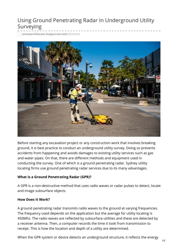
Application • Useful in Construction • Prevent damage to underground lines • Real-time data gives proximity to pipes • Safety Conscious
Challenges • Ground is very lossy medium • Any moisture will absorb most of signal • Requires more power than detection in air • Power Pulse Width • Low end of microwave regime used for detection
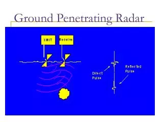
Pulse Width • Pulse short enough to stop transmitting before reflected signal returns to avoid interference • Pulse width = Depth of Penetration / c , where c is the speed of light • Depth of buried lines usually ~ 2m • Short pulse means less energy transmitted
Frequency Calculations • Calculate Skin Depth to ensure most of the power reaches the pipes • No greater than 2 meters • δs = sqrt(2 / (ω*μ*σ) ) • μ = μ0 • σsoil = 1 to 10^-4 S • ω = 2*π*f
Continued….. • Solve the skin depth formula for the frequency, f = 633 MHz • Therefore, the low end of the range of frequencies is 600 MHz • The high end was chosen to be 1000MHz to allow better resolution
FMCW Radar • Frequency Modulated Continuous Wave Radar (FMCW Radar) • Key characteristic • Allows a signal to simultaneously be transmitted and received without interference • Benefit • Pulse width can be increased -- no constraint on when it must end
FMCW Radar The Constant offset between the transmitted signal (solid curve) and received signal (dashed curve) is proportional to the distance from the object
Frequency Modulator • Modulating Signal • Saw tooth from 600MHz to 1000MHz • Carrier Signal • Sine wave • Frequency Modulated Signal • Sine Wave with frequency varying linearly from 600MHz to 1000MHz
Voltage Controlled Oscillator • Benefits • Mobile, can be placed on machinery • Vary frequency with Voltage input • Issues • High Frequency needed • TuningDiode
Building Modulator • Ordered Parts • VCO (MN100EL1648 – ON Semiconductors) • Tuning Diode (MMBV609 – ON Semiconductors) • Create Printed Circuit Board • Surface Mount Parts • Solder Surface Mount Parts • Build Complete Circuit
Providing Continuous Wave Capability Power Divider Transmit Bandpass Filter Mixer LNA Receive Output Signal
Design • Power Divider • 3-port Device • Output ports receive 85/15 Power Ratio • Low Noise Amplifier • Maxim2640 w/ frequency range 400MHz – 2.5GHz • Bandpass Filter • Reject frequencies outside of 500MHz-1GHz • Mixer • Maxim2680 Down converter • Output frequency range: 10 – 500 MHz
Antenna Design • Bow-tie • Operates over necessary range • Simulation software available • Possible to construct, test and tune within allotted time and budget • Alternatives • TEM Horn • More control over directivity, but would be big • Yagi Antenna • More narrow beam, better for detection
Balun • Importance • Matches Impedance of antenna to impedance of line • Minimizes VSWR which corresponds to a wide bandwidth • Length needs to be a quarter wavelength • At 750 MHz, λ/4 ~ 100 mm • Length can be changed to get best impedance match using the Smith Chart • Final Length – 128.23 mm
Modulator Testing • Use wire for 10 nH inductor • Precision issue • Tank Circuit Performance • Tuning Diode less precise at lower Voltage input • Use HP Spectrum Analyzer • Detect Frequency output • Lower frequency than desired • ~520MHz
Continuous Wave Testing • Power Divider provided power to each arm, however well below the desired levels • Bandpass Filter worked for a tighter band than desired • Lack of power from power divider would not have allowed mixer to operate properly
Theory/Reality • First time design and build of this type of circuit • Designed material ahead of class instruction • Damaged a chip • Power Divider not working as intended • Bandpass Filter provides filtering but in a tighter range than intended.
Zm1 Z01 Z0 R Z02 Zm2 Power Divider • Wilkinson Design instead of T-junction • Use Resistor to Provide Isolation • Multiple matching sections to provide broadband matching
Bandpass Filter • Design using Q-functions • Q = 0 / Bandwidth • Allows greater control over the response characteristics • Applied to the stubs
Performance Verification of Antenna • HP 8510 Network Analyzer • Smith Chart to match antenna impedance to line impedance • Change balun length to optimize VSWR • Log Mag Plot to see that antenna resonates in the desired range of frequencies
Cost Analysis • Frequency Modulator • $15 for VCO • $10 for Tuning Diode • Filter, Amplifier, and Mixer • $10 for etching solution • Antenna • $60 brass sheets • $10 for Plexiglas, cables, etc. • Salary
Improvements • Inductor Capacitor tank with high Q-factor • Use techniques learned in class to improve power divider and bandpass filter • Simulate various antenna structures • Take data for many scenarios with various antennas
References • Online Resources • http://www.georadar.com/howitwrk.htm • http://www.ee.ucla.edu/students/archive/fredrick_ms.pdf • http://www.tpub.com/neets/book12 • Books • Surface Penetrating Radar by D.J. Daniels • Microwave Engineering 2nd edition by David M. Pozar. • Simon Haykins, Communication Systems. New York: John Willey & Sons, Inc. 2001, 88-182
Thanks • Professor Bernhard • Professor Chew • Professor Kudeki • Professor Franke • Judy Feng, EM graduate student • Gentlemen in the Machine Shop • Maxim Semiconductors