Download
1 / 32
350 likes | 766 Views
Chapter 3. Crystalline Structure . Seven Systems and Fourteen Lattices Metal Structures Ceramic Structures Polymeric Structures Semiconductor Structures Lattice Positions, Directions, and Planes X-Ray Diffractions. Structure Review .

E N D
Chapter 3. Crystalline Structure • Seven Systems and Fourteen Lattices • Metal Structures • Ceramic Structures • Polymeric Structures • Semiconductor Structures • Lattice Positions, Directions, and Planes • X-Ray Diffractions
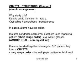
Structure Review • In solid state, particles are bonded together in rigid, crystalline structure. Seven basic crystalline structures are: • cubic: BCC, and FCC • tetragonal: Simple T and BCT • orthorhombic: simple, Body CO, Base CO, and FCO • rhombohedral • hexagonal: hexagonal close packed, FCC closed packed, complex cubic structure (diamond structure) • monoclinic: simple and base-centered • triclinic • Each crystal system has a different axis length and angles that separate the atoms • Table 3.1
Structure Review z c x a b y • Defining components of a general crystal system • lengths of the axes (lattice constants) are a, b, and c • angles between the atom planes are (alpha), (beta), and (gamma) • Components of the crystalline structure
Miller Index z c=2 x a=2 b=3 y • Defining particular plane of the atom with Miller Index • 3 steps to determine the Miller Index • Find the intercepts x = 2, y = 3, and z = 2 from figure • Take the reciprocal of the axis length, 1/2, 1/3, and 1/2 • Find the lowest common multiplier and then multiply the reciprocal • Then, the Miler Index is (3, 2, 3)…… 6*1/2, 6*1/3, 6*1/2.. Note ( ) • Example,
Crystalline Structures • Every crystal lattice structure has its own unit cell • Smallest unit into which a lattice structure can be broken down that sill retains the properties of the whole structure • Table 3.2. Fourteen Crystal (Bravais) Lattices • Simple Cubic, Body-Centered Cubic, Face-Centered Cubic • Simple Tetragonal, BCT • Simple Orthorhombic, BCO, Base CO, FCO, • Rhombohedral • Hexagonal • Simple Monoclinic, BCM, Triclinic
Metal Crystalline Structures • Body centered cubic- atom centered in the cube • Atomic packing factor (APF) is 0.68 and represents the fraction of the unit cell occupied by the two atoms. • Ba, Ce, Li, K, molybdenum (less ductile metals) • Face centered cubic- atom centered on each of the faces • Atomic packing factor (APF) is 0.74 and represents the fraction of the unit cell occupied by the two atoms. • Regular stackings of close-packed planes • Fourth close pack layer lies precisely above the first one • Al, Cu, Au, Pb, Ni, Platinum, Ag (soft metals) • Hexagonal close packed (HCP) • Two atoms are associated with each Bravais lattice point • One atom centered within the unit cell and various fractional atoms at unit cells (four 1/6th atoms and four 1/12th atoms) • Close pack is efficient packing shperes as is the fcc structure. • Atomic packing factor (APF) is 0.74 and represents the fraction of the unit cell occupied by the two atoms. • Regular stackings of close-packed planes • The third close-packed layer lies precisely above the first. • Be, Mg, Ti, Zn, Zr
Metal Crystalline Structures • Hexagonal Close-packed structure (continued) • the distance between atoms in the bases are equal in the hexagonal structure. The bases are perpendicular to the sides. The angle between the sides is 120°. • Graphite has Close-packed hexagonal structure of Carbon • diamond has a form of face-centered closed -pack cubic structure, or complex cubic structure (diamond structure) • other materials with closed-packed hexagonal structure include Be, Cadmium, Co, Mg, Titanium, Zn, Zirconium • Simple tetragonal and body centered tetragonal structures • all atomic planes are still at right angles to each other ,as in cubic structure, however, one dimension is longer than the other two • pure tin: natural tetragonal stucture
Metal Crystalline Structures • Simple orthorhombic • Lengths of all three axis are different. The places of atoms are perpendicular. • Can have body centered, face centered, base centered • Rhombohedral • None of the planes are perpendicular • Monoclinic structure • two atoms of the atomic planes are perpendicular, but the third angle is not 90°. • Triclinic structure • no two places are perpendicular to each other, the distances between the atoms are different, and the angles are not equal • elongated, thin crystal formation
Metal Crystalline Structures • Allotropes • some materials exist in two or more crystalline structures and depends upon temperature and pressure changes. • e.g., pure iron is BCC at normal temp and pressure conditions. Change to FCC if temperature is raised to 1670 F • allotropes are also known as polymorphs • Freezing point of material • As the energy in a liquid system decreases, the forces that are grouping the atoms tend to form distinct patterns which become the characteristic lattice structure of the material. • Formation of lattice crystals produces heat. Lattice grows until it meets another energy block, e.g., lattice structure or container. • Grain Boundary- point at which two lattice structures collide. Boundaries Grains
Crystalline Structures • For lattice growth to start, a nucleus (seed), must be present. • Very pure metals, rapid cooling restricts time for nucleus growth. • Supercooling occurs if the temperature falls below the melting temperature. The temperature increases as the nucleus forms and levels off as the lattice structure evolves. • Crystal size depends upon: metal type, temperature, Cooling rate: Rapid cooling = smaller crystals • Lattice growth occurs more rapidly in directions perpendicular to each other, called Dendritic nature of crystals
Ceramic Crystalline Structures • Wide variety of chemical compositions of ceramics is reflected in their structures • Ionic packing factor- the fraction of the unit cell volume occupied by various cations and anions • Simplest chemical formula, MX, where M is the metallic element and X is the non-metallic element • CsCl structure Fig 3-8 • BCC- built with two ions associated with each lattice point • Does not represent any important ceramic materials • NaCl is shown in Figure 3-9 • Shares structure of many ceramic materials • Two intertwining FCC structures, one of Na ions and one of Cl ions. • Other important ceramic oxides with FCC are • MgO, CaO, FeO, and NiO
Ceramic Crystalline Structures • Other chemical formula, MX2, where M is the metallic element and X is the non-metallic element • Shares structure of importantceramic materials, Figure 3-10 • CaF2 • Built with an FCC Bravais lattice with three ions (on Ca and two F). • 12 ions (four Ca and 8 F) per unit cell. • Other important ceramic oxides with this structure are • UO2, ThO2, TeO2 [Uranium, Thorium, Tellurium Oxides] • Ref: http://www-tech.mit.edu/Chemicool/ • Silica is the most important ceramic of this form, MX2. • Structure is not simple because it is not one structure but many depending upon temperature and pressure (like iron phase diagram) • Example, cristobalite (fig 3-11) • Built upon an FCC Bravais lattice with 6 ions (two Si and 4 O ions) • 24 ions per unit cell • Continuously connected network of SiO4 tetrahedra (Note: the sharing of O2 ions by adjacent tetrahedra gives the overall chemical formula, SiO2
Ceramic Crystalline Structures • Other chemical formula, M2X3, where M is the metallic element and X is the non-metallic element • Important material- Corundum (Al2O3) • Rhombohedral Bracais lattice, Fig 3-13, but closely approximated hexagonal lattice. • 30 ions per lattice with 12 Al and 18 O. • Stucture similar to HCP • Close-packed O– sheets with two-thirds of the small interstices between sheets filled with Al+++. • Cr2O3 and Fe2O3 have corundum structure
Ceramic Crystalline Structures • Other chemical formula, M’M”X3, where M’ and M” are the metallic elements and X is the non-metallic element • Important material- Perovskite (CaTiO3) • Simple cubic Bracais lattice, Fig 3-14, • Different atoms occupy the corner (Ca++), body centered (Ti4+), and face centered (O--) positions • 5 ions per lattice point with one Ca, one Ti, and three O per unit cell. • Properties • Have important ferroelectric and piezoelectric properties • Related to the relative locations of cations and anions as a function of T • Other chemical formula, M’M”2X4, involves magnetic ceramics based on the spinel structure (MgAl2O4)- Figure 3-15 • 56 ions per unit cell with 8 Mg, 16 Al, and 32 O • Important materials- NiAl2O4, ZnAl2O4, and ZnFe2O4 • Mg are in tetrahedral positions that are coordinated by 4 oxygens with the Al in octrahedral positions • Other chemical formula, M’’(M’M”)X4, include Fe(MgFe)O4, FeFe2O4 Fe(NiFe)O4, and many other commercially important ferrites or ceramics
Silicate Structures • Chemical reaction of SiO2 with other ceramic oxides • Nature of silicate structures is the traditional oxides tend to break up the continuity of the SiO4 tetrahedra connections. • The remaining connectedness of tetrahedra may be in the form of silicate chains or sheets. • Example, Fig 3-16. • Kaolinite structure, [2(OH)4Al2Si2O5] is a hydrated aluminosilicate and a good example of clay mineral • Structure is typical of sheet silicates • Built on triclinic Bravais lattice and two laolinite molecules per unit cell • Many clay minerals have a platelike or flaky structure (fig 3-17) due to the crystal structure. • Graphite- Exceptions to general description of ceramics as compounds. • Layered crystal structure of carbon at room temperature- Fig 3-18 • Graphite is monoatomic it is more ceramic than metallic • Hexagonal rings of C are bonded strongly with covalent bonds. • Bonds between layers are of van der Waals type accounting for graphite’s friable nature and use as dry lubricant. • Diamond is cubic structure of C (Fig 3-23
Carbon/Graphite Fibers • Need for reinforcement fibers with strength and modulii higher than those of glass fibers has led to development of carbon • Thomas Edison used carbon fibers as a filament for electric light bulb • High modulus carbon fibers first used in the 1950s • Carbon and graphite are based on layered structures of hexagonal rings of carbon • Graphite fibers are carbon fibers that • Have been heat treated to above 3000°F that causes 3 dimensional ordering of the atoms and • Have carbon contents GREATER than 99% • Have tensile modulus of 344 Gpa (50Mpsi)
Carbon/Graphite Fibers • Manufacturing Process • Current preferred methods of producing carbon fibers are from polyacrylonitrile (PAN), rayon (regenerated cellulose), and pitch. • PAN • Have good properties with a low cost for the standard modulus carbon • High modulus carbon is higher in cost because high temperatures required • PITCH • Lower in cost than PAN fibers but can not reach properties of PAN • Some Pitch based fibers have ultra high modulus (725 GPa versus 350GPa) but low strength and high cost (Table 3-2)
Carbon/Graphite Fibers • PAN Manufacturing Process Figures 3-3 and 3-4 • Polyacrylonitrile (PAN) is commercially available textile fiber and is a ready made starting material for PAN-based carbon fibers • Stabilized by thermosetting (crosslinking) so that the polymers do not melt in subsequent processing steps. PAN fibers are stretched as well • Carbonize: Fibers are pyrolyzed until transformed into all-carbon • Heated fibers 1800°F yields PAN fibers at 94% carbon and 6% nitrogen • Heated to 2300°F to remove nitrogen yields carbon at 99.7% Carbon • Graphitize: Carried out at temperatures greater than 3200° F to • Improve tensile modulus by improving crystalline structure and three dimensional nature of the structure. • Fibers are surface treated • Sizing agent is applied • Finish is applied • Coupling agent is applied • Fibers are wound up for shipment
Carbon/Graphite Fibers • PITCH Manufacturing Process Figure 3-3 • Pitch must be converted into a suitable fiber from petroleum tar • Pitch is converted to a fiber by going through a meso-phase where the polymer chains are somewhat oriented though is a liquid state (liquid crystal phase) • Orientation is responsible for the ease of consolidation of pitch into carbon • Stabilized by thermosetting (crosslinking) so that the polymers do not melt in subsequent processing steps • Carbonize: Fibers are pyrolyzed until transformed into all-carbon • Heated fibers 1800°F • Heated to 2300°F • Graphitize: Carried out at temperatures greater than 3200° F to • Improve tensile modulus by improving crystalline structure and three dimensional nature of the structure. • Fibers are surface treated • Sizing agent is applied • Finish is applied • Coupling agent is applied • Fibers are wound up for shipment
Carbon Fiber Mechanical Properties • Table 3-2
Ceramic Crystalline Structures • Diamond
States of Thermoplastic Polymers • Amorphous- Molecular structure is incapable of forming regular order (crystallizing) with molecules or portions of molecules regularly stacked in crystal-like fashion. • A - morphous (with-out shape) • Molecular arrangement is randomly twisted, kinked, and coiled
Amorphous Materials • PVC Amorphous • PS Amorphous • Acrylics Amorphous • ABS Amorphous • Polycarbonate Amorphous • Phenoxy Amorphous • PPO Amorphous • SAN Amorphous • Polyacrylates Amorphous
States of Thermoplastic Polymers • Crystalline- Molecular structure forms regular order (crystals) with molecules or portions of molecules regularly stacked in crystal-like fashion. • Very high crystallinity is rarely achieved in bulk polymers • Most crystalline polymers are semi-crystalline because regions are crystalline and regions are amorphous • Molecular arrangement is arranged in a ordered state
Crystalline Materials • LDPE Crystalline • HDPE Crystalline • PP Crystalline • PET Crystalline • PBT Crystalline • Polyamides Crystalline • PMO Crystalline • PEEK Crystalline • PPS Crystalline • PTFE Crystalline • LCP (Kevlar) Crystalline
Factors Affecting Crystallinity • Cooling Rate from mold temperatures • Barrel temperatures • Injection Pressures • Drawing rate and fiber spinning: Manufacturing of thermoplastic fibers causes Crystallinity • Application of tensile stress for crystallization of rubber • Processing can produce an amorphous structure from a semi-crystalline material • Clear PET bottles for soda • Clear Polyethylene plastic bags
X-Ray Diffraction • X-ray diffraction is used to determine the crystalline structure of materials. • Diffraction is the result of radiation’s being scattered by a regular array of scattering centers whose spacing is about the same as the wavelength of the radiation. • Example, parallel scratch lines spaced repeatedly about 1 m apart causes diffraction of the visible light (electromagnetic radiation with a wavelength just under 1 m. • The diffraction grating causes the light to be scattered with a strong intensity in a few directions (Fig. 3-33) • Phenomenon in which the atoms of a crystal, by virtue of their uniform spacing, cause an interference pattern of the waves in an incident beam of X rays. • The crystal's atomic planes act on the X rays in the same way a uniformly ruled grating acts on a beam of light (see polarization). • The interference pattern is specific to each substance and gives information on the structure of the atoms or molecules in the crystal.
X-Ray Diffraction • Appendix 2 shows that atoms and ions are on the order of 0.1 nm in size • Crystal structures as being diffraction gratings on a sub nm scale. • X-ray diffraction characterizes crystalline structures, because • Fig 3-34. Portion of electromagnetic spectrum with a wavelength in this range is x-radiation (compared to 1000-nm range for visible light. • In x-rays, atoms are the scattering centers. • Mechanism is the interaction of photon of electromagnetic radiation with an orbital electron in the atom. • A crystal acts as a 3-dimensional diffraction grating, repeated stacking of crystal planes serves the same function serves the same purpose as the parallel scratch lines in Fig 3-33. • For diffraction to occur, x-ray beams scattered off adjacent crystal planes must be in phase. Otherwise, destructive interference of waves occurs which blocks the scattering pattern. (no intensity)
Miller Index z c=2 x a=2 b=3 y • Defining particular plane of the atom with Miller Index • 3 steps to determine the Miller Index • Find the intercepts x = 2, y = 3, and z = 2 from figure • Take the reciprocal of the axis length, 1/2, 1/3, and 1/2 • Find the lowest common multiplier and then multiply the reciprocal • Then, the Miler Index is (3, 2, 3)…… 6*1/2, 6*1/3, 6*1/2.. Note ( ) • Example,
X-Ray Diffraction • Bragg equation relates the spacing between adjacent crystal planes and the angle of diffraction (Bragg angle). • n = 2d sin , Bragg’s Law, • Where d is the spacing between adjacent crystal planes and is the angle of scattering. is the wavelength of the x-ray beam. 2 is the diffraction angle. • Note: William Bragg (1862-1942) and son were first to demonstrate the power of x-ray diffraction by identifying the chemical structure of NaCl. Today over 70,000 materials have been identified. • Magnitude of interplanar spacing, d, is a direct function of the Miller indices for the plane For a cubic system, the relationship is simple. • The spacing between adjacent hkl planes is dhkl = a… (h2+k2+l2) • Where a is the lattice parameter )edge of the unit cell
X-Ray Diffraction • Crystal structures with nonprimitive unit cells have atoms at additional lattice sites located along a unit cell edge, within a unit cell face, or in the interior of the unit cell. • Extra scattering can cause out-of phase scattering which will eliminate the diffraction. • Table 3.4 • Example, Fig 3-39 • Diffraction pattern for a specimen of aluminum powder. • Each peak represents a solution to Bragg’s law. • Powder consists of many small crystal grains of oriented randomly, single wavelength of radiation is used. • The pattern is compared with a database of known diffraction patterns.
X-Ray Diffraction • Corrosion and scale analysis by XRD (X-ray diffraction) • This involves qualitative identification of corrosion products. • The peaks in the diffraction pattern are checked against a database of previously identified phases using a search match program. • Any chemical data you have available helps to narrow the search scope http://www.ktgeo.com/tCS.html