Download
1 / 4
40 likes | 54 Views
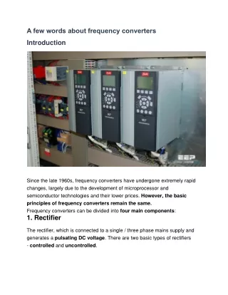
The rectifier, which is connected to a single / three phase mains supply and generates a pulsating DC voltage. There are two basic types of rectifiers - controlled and uncontrolled.

E N D
A few words about frequency converters Introduction Since the late 1960s, frequency converters have undergone extremely rapid changes, largely due to the development of microprocessor and semiconductor technologies and their lower prices. However, the basic principles of frequency converters remain the same. Frequency converters can be divided into four main components: 1. Rectifier The rectifier, which is connected to a single / three phase mains supply and generates a pulsating DC voltage. There are two basic types of rectifiers - controlled and uncontrolled.
2.intermediate circuit The intermediate circuit There are three types: 1.One that converts the rectifier voltage to direct current. 2.One that stabilizes or smooths the pulsed DC voltage and makes it available to the inverter. 3.One, which converts the constant DC voltage of the rectifier to a variable AC voltage. 3.inverter The inverter that generates the frequency of the motor voltage. Some inverters can also convert constant DC voltage to variable AC voltage. Control circuit Control circuit electronics, which transmit signals to and receive signals from the rectifier, intermediate circuit, and inverter. The parts checked in detail depend on the design of the individual frequency converter (see figure 2). What all frequency converters have in common is that the control circuit uses signals to turn the semiconductors on or off in the inverter. Frequency
converters are divided according to the switching scheme that controls the supply voltage to the motor. Figure 2 shows the different design / control principles: 1.Is a controlled rectifier, 2.Is an uncontrolled rectifier, 3.Is an intermediate circuit with variable direct current, 4.Is an intermediate circuit with constant direct voltage, 5.Is an intermediate circuit with variable direct current, 6.Is a PAM inverter and 7.PWM inverter. Current source changeover: CSI (1 + 3 + 6) Amplitude and pulse modulation converter: PAM (1 + 4 + 7) (2 + 5 + 7) Pulse width modulated converter: PWM / VVC plus (2 + 4 + 7) Direct converters, which have no intermediate circuit, should also be briefly mentioned for completeness. These converters are used in the megawatt power range to generate a low frequency power supply directly from the 50 Hz mains and their maximum output frequency is approximately 30 Hz. Burraq Engineering Solutions is providing practically electrical courses in Lahore. We offer PLC course, SOLAR SYSTEM Installation and DESIGN COURSE, ETAP course, DIALAX course, Panel FABRICATION course,
VFD course, ADVANCED Course Panel, SWITCHERGEAR design course, Building Electrical design course and all electrical diploma courses in Lahore