Download
1 / 7
0 likes | 96 Views
Impedance, Z, is defined as the ratio of voltage difference to current flowing between any two nodes in an ac circuit. For more information, kindly visit: https://www.expertsminds.com/

E N D
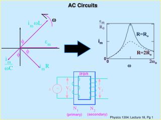
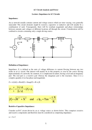
AC Circuit Analysis and Power Lecture: Impedance in AC Circuits Impedance: An ac network usually contains current and voltage sources which are time varying, very generally sinusoidal. The circuit elements might be resistive, capacitive or inductive and will usually be a combination of such. Consequently, there will be resultant magnitude and phase relationships between currents and voltages at different locations all through the circuit. Consideration will be confined to circuits containing only a single driving source. i(t) L2 R1 R2 C1 Z ~ R3 V(t) C2 L1 Definition of Impedance: Impedance, Z, is defined as the ratio of voltage difference to current flowing between any two nodes in an ac circuit. Our interest will mainly be in this property as seen by the source driving input terminals of a network. In common, it is complicated in nature, having a real and an imaginary part. The real part is a resistive part whereas the imaginary part is the reactance. Since it is a complex quantity it too has phase and magnitude. Z = v(t)/i(t) = Real(Z) + Imag(Z) = R ± jX v i v = = = v Z Ζ Ζ i i X − = + = 2 2 1 R X and Tan Ζ Ζ R Resistive-Capacitive Impedance: Consider an R-C circuit driven by an ac voltage source as shown below. This comprises resistive and reactive components and therefore must be considered as comprising impedance. ω = 2 п f 1
f = 50 Hz VR i(t) R = 1kΩ Z ~ VC C = 1µF 1Sinωt V(t) Since the elements are in series, the voltage drops across them should sum to the voltage of source driving the circuit and hence: Z = v(t)/i(t) and v(t) = vR(t) + vC(t) Then, Z = [vR(t) + vC(t)]/i(t) = [vR(t)/i(t)] + [vC(t)/i(t)] = ZR + ZC Z = R - jXC = R – j (1/ ωC) This can be seen that the overall impedance of the network is provided by the impedances of an individual element in series. Therefore, these are simply added altogether just as in the situation of purely resistive elements in series. This is of interest to establish all the current and voltage relationships that apply to thiscircuit. V(t) = Vmsin ωt = Vm <00 is considered as the reference phase of zero. At first: R = 1KΩ, C = 1μF = 10-6F ω = 2 п f = 2 x 3.14 x 50 = 314 rad/s XC = 1/ωC = 1/(314 x 10-6) = 106/314 = 3184.7 = 3.18 K Ω For the circuit given: Z = R + 1/j ωC = R – j(1/j ωC) Z = 1KΩ - j3.18 KΩ = 103 – j3.18 x 103 Ω In terms of magnitude and phase: |Z| = √106 + (3.18)2 x 106 = √11.1 x 106 = 3.33 KΩ 2
− 3 3.18 x 10 3 − − = = − = − 1 1 Tan Tan 3.18 72.5 Ζ 1 x 10 Consider the current i: V i = = V Sin V 0 ωt = m m − 1 1 Ζ − R j R j ωC ωC Treating Sin ωt as the reference zero phase Rationalising: Then, i = = = 0.0922 0.3mA 72.8 i Consider a simpler alternative: 3
V V V ( ) = = − = − v i m i v Ζ Ζ Ζ Ζ Ζ Ζ 1 = − − = 72.5 i 72.5 0.3 mA i 3.33kΩ Then This signifies we only require doing one complex number computation. A phasor plot of all currents and voltages concerned is as shown below. j i VR 72.5o V Reference 17.5o VC -j When the driving source voltage is taken as reference V shown by i in the diagram. The voltage across resistor, VR, should have similar phase as the current i as it is purely real. The voltage across capacitor, VC should lag the current via it by 90o and thus lags the source voltage by 17.5o. o 0 , the current leads this by 72.5o as 4
Combined Resistive-Inductive Impedance: Let consider an R-L circuit driven by the ac voltage source as shown below. This also comprises resistive and reactive components and has related impedance. Ω = 2 п f f = 50 Hz i(t) iL iR Z ~ v(t) L = 500mH VR = VL R = 200 Ω 1Sinωt It is as well of interest to establish all the current and voltage relationships that apply to this circuit for comparison. v(t) = Vm sin ωt = Vm <00 taking this as reference. If, R = 200 Ω, L = 500 mH, Vm = 1V and f = 50 Hz Then, ω = 2 п f = 314 rad/s XL = ωL = 314 x 500 x 10-3 = 0.5 x 314 = 157 Ω For the circuit given the inductor and resistor are in parallel and the source voltage emerges across both and hence: Z = v(t)/i(t) and v(t) = vR(t) = vL(t) The current drawn from supply is shared among the two elements and hence: i(t) = iR(t) + iL(t) 5
Z = v(t)/i(t) = [v(t)]/[iR(t) + iL(t)] And hence, 1/Z = [iR(t) + iL(t)]/v(t) = [iR(t)/v(t)] + [iL(t)/v(t)] = (1/ZR) + (1/ZL) 1/Z = 1/R + 1/jωL Where there are just two elements this can be opportunely simplified: 1/Z = (ZL + ZR)/ZRZL Z = ZRZL/(ZL + ZR) = (j ωLR)/(R + jωL) Rationalising: Z = 76.25 + j 97.14 Ω In terms of phase and magnitude: |Z| = √5814 + 9436 = 123.5 Ω 97.14 − − = = = 1 1 Tan Tan 1.27 51.78 2 76.25 To calculate the current drawn from the supply: v(t) i(t) = = o 1 0 1 . 8 = − o 51 78 . mA o Z 123 5 . 51 87 . The current flowing via the resistor should be in phase with the voltage across it, that is the source voltage, v(t), and thus has a phase of zero. 6
|iR| = |v(t)|/R = 1<00/R = 1/200 = 5 < 00 mA The current flowing via the inductor should lag the voltage across it, that again is the source voltage, v(t), and thus this has a phase of -90O. iL = v(t)/ (ωL ∟900) = 1/157∟900 = 6.4 ∟-900 mA The phase relationships of all voltages and currents are shown in the phasor diagram below. V, VL and VR all have similar phase which is that of input source voltage, that is treated as the reference zero phase. The current flowing via the resistor R also has similar zero phase. The current via the inductor lags the voltage across it and thus has a phase of -90o. Ultimately the current drawn from the supply, i, is shown lagging the source voltage by 51.78o as computed. j V, VL ,VR iR 51.87o iL i -j Reference: https://www.expertsminds.com/ https://www.tutorsglobe.com/ 7