
CMM-PPT
E N D
Presentation Transcript
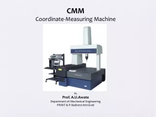
CMM Coordinate-Measuring Machine By Prof. A.U.Awate Department of Mechanical Engineering PRMIT & R Badnera-Amravati
CMM is a 3D device for measuring the physical geometrical characteristics of an object. • CMM is a machine which takes readings in six degrees of freedom and displays these readings in mathematical form. • CMM is a specialized form of industrial robot
Parts • CMM include three main components: • 1.Main Structure • which include three axes of motion • 2. Probing system • 3. Data collection and reduction system • Application software • Machine controller • Desktop computer
1.Main Structure • Gantry type • Advantage: • Measurement of large size parts • Disadvantage: • Geometric changes caused by non-uniform temperature distribution owing to their large size. • Application: • Heavy machine construction, • car body and mold making sectors • of the automotive industry, • measuring wind tunnel models.
1.Main Structure • Cantilever type • Advantage: • Large measuring range • Maximum accessibility • Disadvantage: • Bending of the cantilever above the measuring area • Application: • For checking sheet metal, cast iron and steel parts in the automotive industry, aircraft construction and shipbuilding.
1.Main Structure • Column type • (horizontal arm type) • Advantage: • High accelerations and speeds • owing to the large supporting base • of the column and its low weight • Disadvantage: • Suitable for small measuring ranges • only since the projecting part of the columnmust have short length due to its rigidity. • Application: • In precision measurements • on gages and master parts.
1.Main Structure • Bridge type • Advantage: • Most widely used • High rigidity owing to compact bridge design and thus small measuring deviations. • Disadvantage: • Limited accessibility caused by the bridge. • Application: • For medium to large measuring range
Portable CMM Have six rotary axes with rotary encoders, instead of linear axes. Less accurate than a bridge type CMM Use angular measurements taken at the joints of the arm to calculate the position of the stylus tip. Can reach the insides of complex parts Applications: Reverse engineering, rapid prototyping, and large-scale inspection of low-volume parts are ideally suited for portable CMMs
CMM Features • Granite Table • Structurally and thermally stable material • Low porosity • Low moisture absorption • Low coeff. of thermal expansion • Superior strength • Uniformity of texture • Non-glaring surface • M8 threaded table inserts
CMM Features • Air bearings • Provided for ensuring friction free travel to all axes • Compressed air is forced through a series of very small holes in a flat bearing surface to provide a smooth but controlled air cushionon which the CMM can move in a frictionless manner
CMM Features • Each axis is fitted with a reference system and a linear measurement transducer for positional feedback. • (0.5 micron resolution) • Passive vibration damping system isolates external vibrations • FEA designed bridge beam extrusion provides optimum M.I. for minimum deflection when operating at high accelerations
2. Probing system • The touch probe forms the sensing device on the end of the quill • Mechanical probe • Contact type • Soldering a hard ball to the end of a shaft • No control on measuring pressure • Electronic touch trigger probe • Contact type • Stylus is spring-loaded with ruby ball at the tip • As the probe touched the surface of the component the stylus deflected and simultaneously sent the XYZ coordinate information to the computer • Optical probes and Laser probes • Non-Contact type • White light/ Laser beam is projected against the surface of the part • Better for scanning
2. Probing system • Pre-travel variation (PTV) • Pre-travel is the amount of stylus bending • at the point that a trigger occurs. • Pre-Travel depends on • Contact Force FCneeded to overcome • Spring Force FS • Length L and stiffness of the stylus • Direction of measurement R • Pre-travel in the Z direction tends to be small • despite the higher forces • Pre-travel can be compensated by probe calibration. • Adatum feature (of known size and position) is • measured to establish the average pre-travel
2. Probing system • Stylus modules
2. Probing system • Qualifying Probe Tips • Correction for Tip Radius • CMM detects dimension from and to the center of the tip (ruby ball) which calls for correction for tip radius. • Each recorded value is corrected for tip radius.
3. Data collection and reduction system • Application software • PC-DMIS CMM • Dimensional Measuring Interface Standardis the world’s leading metrology software • PC-DMIS PRO • Full-featured metrology software system • without CAD capabilities. • PC-DMIS CAD • It adds CAD capabilities to PC-DMIS PRO. • It allows import and export CAD modules • Possible to develop, test and debug part programs directly on CAD models • Compares the measured data directly to the CAD model • Lets graphically test and debug inspection routines • PC-DMIS CAD++ • Handles difficult scanning tasks (contact & non contact type) • and supports sophisticated scanning devices
3. Data collection and reduction system • Application software Modules • PC-DMIS CMM • PC-DMIS Planner • PC-DMIS Gear • PC-DMIS Blade • PC-DMIS NC • PC-DMIS Portable • PC-DMIS Vision
3. Data collection and reduction system • Application software • Alignment • PC-DEMIS mathematically relates the Part Coordinate Systemand Machine Coordinate System.
3. Data collection and reduction system • Application software • Measured and Constructed Features
3. Data collection and reduction system • CMM controller • Controller is the heart of CMM • Provides precise control of the • motion of the machine • Interfacing to sensors and • with the metrology software.
CMM Applications • Metrology • Linear Measurement (Measured and Constructed Features) • Angular Measurement (Measured and Constructed Features) • Geometrical Features • Profile Checking • Stages of Inspection • Receiving • In-proses • Final • Mode of Inspection Operation • Manual • Automated (DCC) • Purpose of Inspection • First-piece approval • Process Control • Pre-assembly qualification of parts • Reverse Engineering • Location of Inspection • Standard Room • Machine Shop • on Site