Download
1 / 59
590 likes | 835 Views
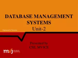
Unit 2. Hardware Systems. 2.1 Processor and Memory 2.2 Peripherals 2.3 Storage devices 2.4 Putting Together the Hardware Components 2.5 Improving Computer performance. Overview of Hardware Components. Microprocessor (executes instructions). Storage Devices (permanently store data

E N D
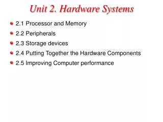
Unit 2. Hardware Systems • 2.1 Processor and Memory • 2.2 Peripherals • 2.3 Storage devices • 2.4 Putting Together the Hardware Components • 2.5 Improving Computer performance
Overview of Hardware Components Microprocessor (executes instructions) Storage Devices (permanently store data and application programs) Chipset (controls data flow) Main Memory (temporarily stores data and program instructions while the computer is running) Legend Peripherals (input/output) Components Data Path
How a File is Displayed Microprocessor (executes instructions) Storage Devices (permanently store data and application programs) Main Memory (temporarily stores data and program instructions while the computer is running) 1 3 4 2 Chipset Legend Peripherals (input/output) Components Data Path • The microprocessor sends instructions to the storage devices (via the chipset) requesting the specified file to be loaded into main memory. • The storage devices send the file through the chipset to main memory. • The microprocessor fetches • the file contents from main • memory. • The microprocessor sends the display data to the monitor • via the chipset.
Components inside the System Unit A. Motherboard H. Disk drives B. Power supply C. Microprocessor (underneath a cooling fan) G. IDE cable D. Expansion slot E. Expansion card F. Chipset
Memory Fetch-Execute Cycle Let R = X + Y Number 1 (X) Number 2 (Y) Result R Control Unit Step 1. Control unit fetches instruction Step 3. Control unit executes the instruction by directing the ALU to add the 2 numbers in the registers 1 and 2 then store the result in the accumulator. Step 2. Control unit interprets the instruction and sends the 2 numbers to be added into the appropriate registers in the ALU. Step 4. Result is stored back in memory. ALU Register 1 (contains Number 1) Register 2 (contains Number 2) Accumulator (Result of Number 1 + Number 2)
The Microprocessor CPU (ALU, Registers, Control unit) L1 cache L2 cache (usually on CPU) Microprocessor Storage Devices (permanently store data and application programs) Chipset (controls data flow) Main Memory (temporarily stores data and program instructions while the computer is running) Legend Peripherals (input/output) Components Data Path
Processor Performance • Rate at which the instructions are processed (clock rate) • Measured in Hertz • 1 Hertz - one cycle per second • Processor clock rate measured in MHz • Machines are compared based on their clock speed or number of instructions per second (ISP). • This measure depends on both the number of cycles per second and the mix of instructions executed. • Measure of processor performance is benchmarking. • ZDNet is organization which has a set of useful benchmarks
Types of Memory Memory Main Memory Microprocessor (executes instructions) RAM (instructions to be executed after computer is booted) Boot Memory ROM (instructions needed to boot the computer) Storage Devices (permanently store data and application programs) Chipset (controls data flow) CMOS (Configuration information used in the boot process) Legend Peripherals (input/output) Components Data Path
Types of Memory (continued) • RAM (random access memory) is a temporary holding area for both data and instructions. It is also referred to as main memory. • Data in RAM is lost when the computer is turned off. • Measured by its memory capacity and latency. • Capacityis the maximum number of bits or bytes that can be stored. The capacity of RAM is typically measured in megabytes (MB). Many computers have RAM capacity of 128MB or more. • Latency is the delay between the time when the memory device receives an address and the time when the first bit of data is available from the memory device. This delay is also referred to as access time. Latency is typically measured in nanoseconds (ns), billionth of a second (10-9 sec). Latency measures the speed of RAM.
DRAM • DRAM - Dynamic RAM is a common type of RAM. • Made of an integrated circuit (IC), composed of millions of transistors and capacitors. • A capacitor can hold electrons. An empty capacitor represents a zero, and a non-empty capacitor represents a one. Each capacitor can register either a zero or a one for a memory cell, storing one bit of data. • The transistor is like a switch that controls whether the capacitor's state (charged or not charged, 1 or 0) is to be read or changed. • However, a capacitor is like a cup that leaks, in order to keep its charge, the memory control needs to be recharged or refreshed periodically. Therefore, it is called the dynamic RAM because its state is not constant. • Refreshing capacitors also takes time and slows down memory.
DRAM (continued) • SDRAM(Synchronous Dynamic RAM) • Used in many personal computers • Fast and relatively inexpensive • Synchronized to the clock so that data can be sent to the CPU at each tick of the clock, increasing the number of instructions the processor can execute within a given time • DDR SDRAM (Double Data Rate SDRAM) • Transfers twice the amount of data per clock cycle compared to SDRAM • Capacity is up to 2 GB • RDRAM (Rambus Dynamic RAM) • Higher bandwidth than SDRAM • More expensive compared to SDRAM • Enhances the performance of applications that access large amounts of data through memory, i.e. real-time video and video editing • SRAM(Static RAM) • Uses transistors to store data • Because SRAM does not use capacitors, reading data from SRAM does not require recharging the capacitors. Therefore, it is faster than DRAM. • Holds fewer bits and costs more compared to DRAM of the same size • Used in the cache because it is fast and cache does not require a large memory capacity
Which Memory Device to Use? ROM no Need to maintain data when power is off? Need to store configura-tion information? Need to update information? yes no Start no yes yes RAM CMOS EEPROM/ Flash
Processor and Memory Memory Microprocessor Main Memory CPU (ALU, Registers, Control unit) RAM (instructions to be executed when the computer is running) L1 cache L2 cache (usually on CPU) Boot Memory ROM (instructions needed to boot the computer) Storage Devices (permanently store data and application programs) Chipset (controls data flow) CMOS (Configuration information used during the boot process) Legend Peripherals (input/output) Components Data Path
Peripherals Storage Devices Microprocessor (executes instructions) Storage Devices (permanently store data and application programs) Main Memory (temporarily stores data and program instructions while the computer is running) Chipset Peripherals Legend Parallel modem Component PS-2 sound card Memory Port PCI Slots Expansion Card video card USB Expansion Slot FireWire AGP Slot Peripheral Device Modem Monitor Digital camera Camcorder Printer Bus Speaker Scanner Mouse Disk drive
Expansion Slot, Card, and Port • An expansion slot is a slit-like socket on the motherboard into which a circuit board can be inserted. • The circuit board is called the expansion card. • Used to extend the capability of a computer • Examples: sound card and the video card • Also provides port(s), which are connector(s) between the expansion card and the peripheral device.
Expansion Slots • The two most common types of expansion slots are Peripheral Component Interconnect (PCI) and Accelerated Graphics Port (AGP). • PCI (Peripheral Component Interconnect )slot • Can hold a variety of expansion cards such as a sound card or an Ethernet card • AGP (Accelerated Graphics Port)slot • Primarily used for graphics cards • PCMCIA (personal computer memory card international association) slot • Used for laptops in place of PCI slots on desktop computers • Relatively smaller than a PCI slot
Expansion Cards • Small circuit boards that control the peripheral devices • Graphics Cards • Takes signals from the processor and displays the graphics, images in the monitor • Sound Cards • Converts analog sound signals to digital and vice versa • Modem • Transmits data over phone or cable lines • Ethernet card • Serves as the interface to a Local Area Network (LAN), a common network technology allowing users access to network resources such as the Internet, email, shared printers, etc. • Transfers data at a rate of 10 Mb/s • Newer versions of Ethernet called "Fast Ethernet" and "Gigabit Ethernet" support data rates of 100 Mb/s and 1 Gb/s (1000 Mb/s).
Expansion Ports • Ports are connectors that enable signals to be passed in and out of a computer or peripheral device. • Cables from peripheral devices connect to ports of a computer system.
Different Types of Ports • PS/2 port, also known as serial port • Transfers data one bit at a time • Uses a 6-pin, mini-DIN configuration, which look like a small, round port • Used to be the de facto standard for keyboard and mouse connections, however, they are gradually being replaced by USB ports. • DB-9 port • Also becoming obsolete • Used to connect PDA devices before the advent of USB ports • Connects external modem, barcode scanner, and other older electronic devices • DB-25F, also known as Parallel port • Transfers data one byte at a time • Requires a 25-pin male connector (DB-25M) on the cable • Can be used for printers or external drives
USB and FireWire • USB (Universal Serial Bus) port • Appears on desktop systems and laptops • Can connect up to 127 devices via a USB hub, which provides multiple USB ports (e.g. mouse, keyboard, scanner, printer, digital camera, and hard disk drive) • Supports "hot connectivity," which allows peripherals to be connected to the system, configured, and used without restarting the machine • Replacing serial and parallel ports • FireWire • Faster data transfer rate and more expensive compared to USB (50MBps versus 1.5 MBps) • Supports up to 63 devices • Intended for data-intensive devices such as DVD players and digital camcorders • Peripheral devices can be connected via chaining. • Supports hot connectivity • Note: In response to FireWire's fast data transfer rate, USB-2 is developed with a data transfer rate of 60 MBps. To compete with USB, FireWire 2 is developed with a data transfer rate of 100 MBps.
Buses Microprocessor (executes instructions) Storage Devices F r o n t s i d e Storage Devices (permanently store data and application programs) Main Memory (temporarily stores data and program instructions while the computer is running) Chipset PCI Memory PC I AGP USB F i r eWi r e Peripherals Legend Parallel modem Component PS-2 sound card Memory Port PCI Slots Expansion Card video card USB Expansion Slot FireWire AGP Slot Peripheral Device Phone line Monitor Digital camera Camcorder Printer Bus Speaker, microphone Scanner Mouse, keyboard Disk drive
Bus • A bus is a pathway through which data is transferred from one part of a computer to another. • Consists of the data bus and the address bus. • The data bus transfers the data itself, while the address bus transfers information about where the data is to go. • Has a width, a speed, and a transfer rate. • The width, also called the word size, of a bus is measured in bits. • The speed of a bus is measured in hertz (Hz), or cycles per second. • Transfer rate is the measure of how much data may be moved from one device to another in one second. • Transfer rate can be increased by transferring data multiple times during a cycle or increasing the number of channels used to transfer data.
Different Types of Buses • Front Side bus • Bus on the motherboard that transfers data between the CPU and the chipset • Memory Buses: RAM bus andDRAM bus • Usually transfers data multiple times during a clock cycle or uses multiple channels to transmit data to increase data transfer rate to match that of the CPU. • ISA(Industry Standard Architecture) • Becoming obsolete • Word size or width of the data path is 16 bits, running at a mere 8 MHz • PCI(Peripheral Component Interconnect) • Predominant bus for newer systems • 32 bits (standard), running at 33 MHz—giving PCI up to 133MBps of bandwidth • AGP(Accelerated Graphics Port) • Bus architecture similar to that of PCI • Provides video cards with rapid access to the system memory • To date, only used for graphics cards, especially those that perform texture-mapping onto three-dimensional renderings • Very fast, running at 66 MHz with a 32-bit word size, and transferring 266 MBps
Different Types of Buses (continued) • IDE bus • Transfers data between storage devices and the chipset • USB (Universal Serial Bus) and FireWire (IEEE 1394) • Transfer data one bit at a time at a variable pace • Not rated with a MHz speed; rated by peak transfer rate. • USB • Faster than standard serial connections, with a peak transfer rate of 1.5 MBps. • Considered a low-speed bus and is designed to handle low to medium-speed peripherals • An extension to USB-1 is USB-2, which supports data rates up to 60 MBps versus the 1.5 MBps in USB-1; USB-2 is fully compatible with USB-1. • FireWire • High transfer rate designed for high-speed external peripherals such as DVD-ROM and hard disk drives • FireWire 2 (IEEE 1394b) emerged with data rates up to 100 MBps, double that of FireWire 1 (IEEE 1394).
Input Devices • Cameras • Digital Camera • Enables photos taken to be stored in digital form, which can uploaded onto a computer. • Web Camera (webcam) • Captures live video and sends the compressed image stream to the computer or to other computers via the Internet • Digital Camcorders • Record video in digital form, which can be uploaded onto a computer without further loss in image quality • Recorded video can be edited using movie-editing software • Images are more clear than those captured by a webcam, but requires more bandwidth • Uses fireWire jack/interface to enable host computers to provide enough bandwidth for the camcorder • Scanners • Convert a 2-D physical image (for example, a photograph or a paper copy of an image) into a digital image that can be viewed and edited on your computer
Output Devices: Monitors and Projectors • CRT (cathode ray tube) monitors • Used to be the most common type of computer monitors until LCD monitors began to gain popularity • Use three electron beams to create colors, red, green, and blue. To generate the color white, all three beams are fired simultaneously. To create the color black, all three beams are turned off. Other colors are created using different mixtures of these three color beams. • Inexpensive and dependable for displaying images on screen. • Also found in conventional TV sets. • LCD(liquid crystal display) monitors • Produce images by manipulating light within a layer of liquid crystal cells • Also known as flat-panel screens • Compact, lightweight, easy-to-read, and emit less radiation compared to CRT monitors • Used in notebook computers and desktop computers
Projectors • Enable images on the computer screen to be magnified and projected onto a bigger screen • Use two types of technologies • LCD (liquid crystal display) system • Images are projected as light shines through a layer of liquid crystal cells • DLP (digital light processing) system • Uses tiny mirrors that reside on a special microchip called the Digital Micromirror Device (DMD) • Images are smoother and have better contrast than those created using LCD
Printers • Ink Printers • Works by spraying and dyeing the page with color • Rated according to their resolution and color depth • Color depth is the range of colors that any given drop may represent • Resolution is measured in dpi, the number of dots per inch (horizontally or vertically) that a printer can place on a page. Sometimes the dpi is the same both horizontally and vertically, such as 1200 dpi. Other times, the horizontal and vertical dpi differ—as in1440x720 dpi. • Use a four-color process, CMYK (cyan, magenta, yellow, and black), to produce various colors. Sometimes the color black is excluded because it can be produced by mixing the other three colors. • Multiple drops of colors can also be placed on a single dot to produce more colors.
Printers (continued) • Dye-Sublimation Printers • Used to print high-quality images like those at a photo lab • Use solid dyes consisting of the four colors, cyan, magenta, yellow, and black. • Varying mixtures of CMYK color dyes can be used to represent different colors, achieving photo-like quality • The print head heats and vaporizes the dyes to allow them to permeate the glossy surface of the printing paper before they solidify • Laser Printers • Use toner cartridges that contain toner, a colored powder • Uses laser beams to charge the image of the page onto a photoelectric drum • When the paper runs through the printer in between the drum and the toner cartridge, the electro-magnetic charge of the drum picks up the toner and then transfers it to the paper. A heat and pressure system then fuses the powder to the page.
Disk Controller Interfaces Storage Devices Microprocessor (executes instructions) Storage Devices Hard drive Disk Controller I D E CD-ROM Chipset (controls data flow) Main Memory (temporarily stores data and program instructions while the computer is running) DVD-ROM PCI Legend Peripherals (input/output) Components Data Path Bus
IDE Interface • Provides a standard way for storage devices to connect to a computer • The controller for the IDE is usually integrated into the disk or CD-ROM drive, and the controller directs how the hard drive stores and accesses data. • IDE was created as a way to standardize the use of hard drives in computers by combining the controller and the hard drive because having separate controllers and hard drives resulted in poor signal quality and performance. • In 1984, IBM introduced the AT computer with a hard drive had a combined drive and controller. A ribbon cable from the drive/controller combination is used to connect to the system unit, creating the AT Attachment (ATA) interface. • Soon, other vendors started offering IDE drives based on the ATA standard developed by IBM. Thus, IDE became the term that covered the entire range of integrated drive/controller devices. Because almost all IDE drives are ATA-based, the two terms are used interchangeably.
EIDE • EIDE is Enhanced IDE. • Provides a set of two IDE (Integrated Device Electronics) ports. • Primary port and secondary port • Each port attaches to a cable containing two plugs, and each plug can connect to a device. • Total of four devices can be accommodated: two on the primary, and two on the secondary. Primary Master Device Primary IDE Port Primary Slave Device Secondary Master Device Secondary IDE Port Secondary Slave Device
Mass Storage • Slowest access times • Low transfer rates • Located farther from processor • Examples: • Magnetic disks (Hard discs, floppy discs) • Optical disks (CD-ROM) • Magnetic tapes • Advantages of Mass storage devices: • Non-volatile (data remains even after power is turned off) • High storage capacity (billions or trillions of bytes) • Cost per bit is lower than RAM • Use removable media in some cases
MTBF (Mean Time between Failures) • Reliability of the computer component is expressed as MTBF • Calculated by dividing the number of failures by the total hours of observation. • MTBF is somewhat misleading to most consumers. • Effect of Hardware depends on the component fails. • If RAM , monitor or microprocessor fails they can be replaced. • Hard Disc drive failure is serious as all the data are lost.
Optical Media: CDs and DVDs • Advantages of optical technologies: • Reliability: they are less prone to environmental damages. • Usually used as a medium for multimedia presentations that combine sound with graphics, such as movies • A DVD is an enhanced form of a CD. • The two types of disks are physically the same size, but they differ in format.
DVDs • Greater capacity • Narrower tracks • Use blue laser, which has a shorter wavelength than the red laser used by CDs, allowing it to focus on the tinier tracks of the DVD. • Use multiple layers of tracks • Blue laser beams can penetrate the plastic and focus at different depths • Some are dual-layered- two sets of tracks on one side of the disk, one beneath the other. This doubles the capacity of one side of a DVD disk. • A double layer double side (DLDS) DVD drive uses double layers and can read double-sided disks, giving it four times the capacity of a single layer single side (SLSS) drive.
CDs • Two recordable formats, CD-R and CD-RW • Less expensive and have less capacity than a DVD • Most expensive of the CD drives, are priced about the same as a read-only DVD drive. • The more capable DVD-RW drives can be four times the cost of a standard DVD drive. • Many computers (desktops and laptops) today are equipped with CD-RWs and read-only DVD combo drives.
Magnetic Media: Zip Disks • Magnetic media range from some of the smallest capacity storage devices, floppy disks, to the largest capacity devices, hard disk drives. • Zip disks • Removable storage drives produced by Iomega, allow users to store much larger amounts of data than a floppy disk can hold • Capacity ranges from 100 to 750 MB • Better option for graphics and large files. • Were once very popular, and many machines can still be purchased today with a Zip drive as standard equipment. But, their use declined with the wide availability of CD-RW drives and the reduced cost of blank CD-R disks.
Optical Versus Magnetic Media • Optical Media • more durable: not ruined by dust or moisture, nor are they vulnerable to electrical damage (however, they can be damaged by physical damages such as scratches). • MTBF rating (average life expectancy) ranges between 30 and 300 years, while magnetic media utilize magnetic properties that have a MTBF of about 3–7 years. • Magnetic Media • Less expensive per MB than magnetic disks • Can be written and read faster than optical disks (except for floppy disks) • Most hard disk drives offer greater capacity than any currently available optical device
Solid State • Solid-state memory, or flash memory, uses no moving parts inside the chip. • Records data using electronic charges • Rewrites data by applying electric fields using in-circuit wiring to erase predetermined sections of the chip so those areas can be rewritten • Examples: CompactFlash and SmartMedia cards. • CompactFlash card • Uses a controller chip, which can increase performance on devices with slow processors and flash-memory chips. • Storage capacity is between 4MB and 4GB • SmartMedia card • Smaller and thinner than a matchbox • Storage capacity is between 2MB and 256MB
Working Together Microprocessor Main Memory CPU (ALU, Registers, Control unit) Storage Devices Storage Devices RAM (instructions to be executed when the computer is running) L1 cache L2 cache (usually on CPU) Hard drive Boot Memory F r o n t s i d e ROM (instructions needed to boot the computer) Disk Controller I D E CD-ROM Chipset CMOS (Configuration information used during the boot process) DVD-ROM PCI Memory PC I AGP USB F i r eWi r e Legend Peripherals Parallel Component modem PS-2 Memory sound card Port Expansion Card PCI Slots video card Expansion Slot USB FireWire AGP Slot Peripheral Device Phone line Monitor Digital camera Camcorder Printer Bus Disk drive Speaker, microphone Scanner Mouse, keyboard
Major Hardware Components and Their Functionality • CPU executes instructions stored in memory devices. • During the boot process, the CPU fetches instructions from the permanent memory devices, ROM and CMOS. • ROM is read-only memory that stores instructions needed to start up the computer. • CMOS contains system configuration data. • Once the computer is booted, RAM is used to load the rest of the instructions to be executed by the CPU. • Data from storage devices such as the CD-ROM drive and the hard drive are passed through the disk controller. Data can also be stored on hard disk or CD. • Data in the hardware system passes through buses. The buses are the communication channels among components in the system unit. • Peripheral devices such as the keyboard, mouse, joystick, printer, speakers, and microphone are connected to the computer via ports typically in the back of a system unit. • Expansion cards can be plugged into the expansion slots of the computer to extend the functionality of a computer.
How Components Work Together • When a computer processes requests from the user, the CPU directs the other components to carry out specific tasks, and data is passed among components through buses and the chipset. • Scenarios: • To save a file to hard disk, the CPU would pass the data to be saved through the front bus to the chipset. The chipset sends the file data via the PCI bus to the disk controller, which would then send the data to the hard disk storage device. • To open and display an image file, the CPU would signal the disk controller to fetch the image file on the storage device using and store it in RAM. The graphics card would then access the image data and display the image as pixels on the computer monitor.
Researching a Computer System • Researches done through product reviews • Price comparisons • Price and comparisons can be found at: http://www.cnet.com
Online Configuration • Computer hardware vendors have their own web sites • Sites specify system configurations of various products • Priced by components
Moore’s Law • Law can be stated as: Number of transistors on a microchip doubles every 18 months. • Denser the chip => Higher the capacity • Limitations: Chips must be thick enough for the electrons to pass through. • Predictions based on Moore’s Law • Processing power (speed) doubles every 18 months. • Storage capacity of RAM increases exponentially. • Other observations: • Storage capacity of hard disk drives is also increasing exponentially. • Cost for consumers to purchase computer parts is decreasing over time.
Parkinson’s Law of Data • Parkinson's Law of Data: Data expands to fill the space available. • As more memory or disk space becomes available, the demand for more memory or disk space increases accordingly. • As Parkinson's Law predicts, today's operating systems are much more elaborate and require more memory for their own use. • As disk drive capacity increases, people begin using them in new ways (e.g. storing musical recordings, short video clips, and movies).