Download
1 / 20
240 likes | 707 Views
Analysis muffler in the comsol and ansys. Hasan Khodadoost. Abstract.

E N D
Analysis muffler in the comsol and ansys Hasan Khodadoost hasan khodadoost 09103879650
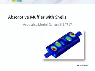
Abstract Although humans may seem to have become accustomed to noise, but they are continuously exposed to its risks. The internal combustion engine is the major source responsible for noise pollution. In an engine, the exhaust noise and the noise produced due to friction of various parts of the engine share maximum contribution to noise pollution. A muffler is a device used to reduce noise within the exhaust system. It is arranged along the exhaust pipe for the purpose of noise attenuation. This paper aims to investigate exhaust noise and provide an improved design for the construction of muffler internal baffles. The pressure loss and the internal flow characteristics of the double mode muffler were analysed by CFD and COMSOL softwares. In addition, the internal pressure distribution, the velocity vector diagram of the dual mode muffler was also obtained. hasan khodadoost 09103879650
Introduction The muffler is back part of the exhaust system. It is used to reduce the noise level emitted by the car exhaust fumes. A certain noise is made during the exhaust. The exhaust gases and the sound waves enter through the down tube. They bounce off the back wall of the muffler and are reflected through a hole into the main body of the muffler. They pass through a set of holes into another chamber, where they turn and go out the last pipe and leave the muffler. A chamber called a resonator is connected to the first chamber by a hole. The resonator contains a specific volume of air and has a specific length that is calculated to produce a wave that cancels out a certain frequency of sound. When a wave hits the hole, part of it continues into the chamber and part of it is reflected. The wave travels through the chamber, hits the back wall of the muffler and bounces back out of the hole. The length of this chamber is calculated so that this wave leaves the resonator chamber just after the next wave reflects off the outside of the chamber [4,5]. hasan khodadoost 09103879650
Introduction: important parameters of muffler There are certain acoustic parameters to determine the performance of a muffler. The parameters are given as: • Noise reduction (NR): Sound Pressure Level (SPL) difference across the muffler meaning actual difference between inlet and outlet. It is an easily measurable parameter but difficult to calculate and a property which is not reliable for muffler design since it depends on the termination and the muffler. • Insertion loss (IL): SPL difference at a point outside the system with and without the muffler present. Insertion loss is not only dependent on the muffler but also on the source impedance and the radiation impedance. Because of this insertion loss is easy to measure and difficult to calculate. • Transmission loss (TL): It is a property of the muffler alone. It is independent of the source (its position and strength). It is easy to predict but difficult to measure since it is very difficult to achieve an anechoic termination, however transmission loss is the most relevant measure to describe the muffler performance. hasan khodadoost 09103879650
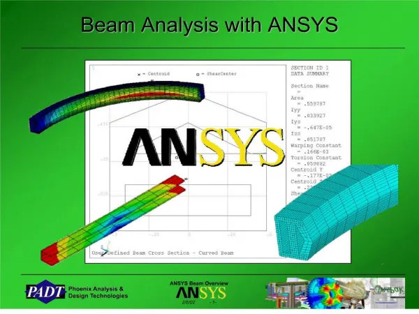
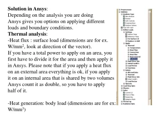
Methodology The fig 4 shows the methodology to achieve the objective of this project. It starts with defining the proper geometry based on present designs and designing it with Solid software package. This model will then be imported into CAE package such as ANSYS. After this we will the mesh the model, apply the required boundary conditions and run the harmonic analysis. Then we will get the harmonic analysis results and we will compare the TL with literature. hasan khodadoost 09103879650
Design of a muffler One important characteristic of mufflers is how much backpressure they produce. Because of all of the turns and holes the exhaust has to go through, mufflers like those in the previous section produce a fairly high backpressure. This subtracts a little from the power of the engine [6]. The noise reduction effect of a muffler can be negatively affected if a high-flow-rate gas flow rapidly rushes out of the muffler after entering it. To prevent this result, the inlet and outlet of the chamber are placed at staggered locations relative to one another, and ducts 1 and 2 share the same central axis. A baffle is inserted inside the chamber to separate the chamber into two cavities. To withstand the impact of a high flow-rate gas flow, a material with relatively high strength should be used to fabricate the baffle.in the Figures below showing the Specification of the muffler in detail [6,7]. hasan khodadoost 09103879650
Design of a muffler hasan khodadoost 09103879650
Design of a muffler in the Figures below showing the Specification of the muffler in detail. hasan khodadoost 09103879650
Design of a muffler • Design of Single Mode Muffler paper Comsol Ansys hasan khodadoost 09103879650
Solution Comsol software: Transmission loss of muffler without the baffle Transmission loss of muffler with the baffle hasan khodadoost 09103879650
Solution • Acoustic pressure Since we know that the single mufflers are good at low frequency ranges i.e., 0-1500 Hz. Now, take a look at figure shown below which is the sound pressure at frequency of 350 Hz. We can say that there is significant difference in pressure from 0.157242 Pa or 85 dB at inlet and after passing through the muffler the pressure at outlet can be seen as a pressure drop of -0.088906 Pa or 72 db. The pressure loss of around 0.068336 Pa or 13 dB is present which is also good. hasan khodadoost 09103879650
Solution • Ansys analyze • iterations in the muffler The muffler design concepts were solved in the CFD code, and on convergence, the models were post-processed to study the flow characteristic in them. The iterations in the muffler are as illustrated in Fig. 12. hasan khodadoost 09103879650
Solution • local pressure The flow of exhaust gases enters the inlet pipe at high velocities which gets blocked by the termination at the end of the pipe. Thus causing heavy recirculation and the gas is forced to exit through the perforation holes. This has an adverse effect of increasing the pressure. It is noticed that the local pressure in the muffler is highest at the end of the inlet tube as seen in Fig. 13. hasan khodadoost 09103879650
Solution • Velocity vector In the first chamber, it is observed that the flow through the inlet pipe holes is not uniform More flow occurs through the holes near to termination. A velocity gradient is observed across the holes and hence the effective porosity in the inlet pipe is reduced. Thus the chamber is not effectively utilized for the expansion and recirculation of the gases. In the second chamber, majority of the gas flow directly enters the outlet pipe, while flow through the baffles is very less. hasan khodadoost 09103879650
Solution • Temperature vector The temperature on most area of the first-stage exhaust muffler lower, while on the side opposite to the airflow direction, the temperature was higher. As to second-stage exhaust muffler, its side directly facing the exhaust port, the temperature was lower, while the opposite side was higher, the temperature on most of the areas. hasan khodadoost 09103879650
Validation The noise reduction effect of the muffler can be more clearly observed in Figure (18). The main goal is to reduce low-frequency noise under this working condition. Therefore, only the low-frequency range (1– 1000 Hz) in which the SPL is relatively high is selected for comparison. At the same frequency, the SPL Equals on average, which further demonstrates that the expansion chamber muffler in this study is effective in noise. hasan khodadoost 09103879650
Optimization • The figure below is a typical simple expansion chamber in the optimization process, the baffle has been moved to the center of Muffler and The simple expansion chamber muffler can be modeled by using a Solid software package. In the study, a single mode exhaust muffler was designed. The three-dimensional model of single-mode exhaust muffler is shown in Fig:(19). hasan khodadoost 09103879650
Optimization As you can see, the resulting data indicates a pressure drop in the muffler and an increase in the output speed, which reduces the volume of the sound pressure level in the system and improves the performance of the system in accordance with the design of the article by liu2018. hasan khodadoost 09103879650
Conclusion • An extensive experimental and numerical methodology has been developed to study the acoustic behaviour of the exhaust system. The Co-Simulation approach of using both CFD and Comsol software to assist in predicting muffler performance, as a result of one cycle of temperature loading, proved to be very useful in developing countermeasures to address issues arising from extreme temperature fluctuations. This analysis is not time dependent. This procedure was shown to be highly effective at all sound wave frequencies. The results clearly show that a stop band has appeared in the desired frequency range using a cylindrical muffler, with the stop band peak TL of 65 dB, which is a significant value, compared to conventional mufflers. This paper discusses in detail, the approach taken in predicting back pressure across a muffler by CFD simulation. The approach adopted focuses on the steps involved in simplifying the problem and attain an acceptable solution with less computational time. This approach can support a broad range of muffler designs and can represent a significant savings of testing and development time. The models presented in this paper show promise to develop a performance prediction capability for muffler systems. hasan khodadoost 09103879650
References • Sathish Kumar, “Linear acoustic modeling and testing of exhaust mufflers”, Master of Science Thesis, Stockholm, Sweden, 2013. • Sabry Allam, “Acoustic Modeling and Testing of Advanced Exhaust System components for Automotive Engines”, Doctoral thesis, KTH, Sweden, 2004. • http://auto.howstuffworks.com/muffler3.htm, retrieved on 15/01/2015 • Rahman, M., Sharmin, T., Hassan, A., Al Nur, A. (2005). Design and Construction of a Muffler for Engine Exhaust Noise Reduction, Proceedings of the International Conference on Mechanical Engineering (ICME2005), 28- 30 December 2005, Dhaka, Bangladesh. • Yasuda, T., Wu, C., Nakagawa, N., Nagamura, K. (2010). Predictions and experimental studies of the tail pipe noise of an automotive muffler using a one dimensional CFD model, Applied Acoustics, 71, 701–707. • Xu, S. L., Shi, Y., and Li, S. C., “Heat Transfer and Thermal Load Analysis of Exhaust Manifold,” Applied Mechanics and Materials (226-228):2240-2244, 2012, doi:10.4028/www. scientific.net/AMM.226-228.2240. • LIU Lian-yun, HAO Zhi-yong, LIU Chi, “CFD analysis of a transfer matrix of exhaust muffler with mean flow and prediction of exhaust noise,” Journal of Zhejiang UniversitySCIENCE A (Applied Physics & Engineering). ISSN 1673-565X (Print); ISSN 1862-1775 (Online). • Sen, S., “Prediction of Flow and Acoustical Performance of an Automotive Exhaust System using 3-D CFD”, SAE Paper No. 2011-01-1068, 2011, doi:10.427/2011-01-1068 • Liu, E., Peng, S., & Yang, T. (2018). Noise-silencing technology for upright venting pipe jet noise, 10(8), 1–15. https://doi.org/10.1177/1687814018794819Alinaghi, M. (2015). Noise Transmission Loss Maximization in Absorptive Muffler with Shells, (June). • Analysis, A., Exhaust, O. F., For, M., & Applications, A. (2015). A Dissertation Report on Submitted by Master of Technology Under the guidance of Prof . Hadiya Pritesh Christ University Faculty of Engineering Department of Mechanical Engineering. • Alinaghi, M. (2015). Noise Transmission Loss Maximization in Absorptive Muffler with Shells, (June). • k.S. Andersen, “Analyzing Muffler Performance Using the Transfer Matrix Method”, Middelfart, Denmark COMSOL Conference, Hannover, 2013. • Attard, W., Watson, H., Konidaris, S., and Khan, M., “Comparing the Performance and Limitations of a Downsized Formula SAE Engine in Normally Aspirated, Supercharged and Turbocharged Modes,” SAE Technical Paper 2006-32-0072, 2006, doi:10.4271/2006-32-0072 • Shojaeifard M H, Ebrahimi-Nejad S and Kamarkhani S 2017 Optimization of exhaust system hangers for reduction of vehicle cabin vibrationsInternational Journal of Automotive Engineering72314–24http://iust.ac.ir/ijae/article-1-390-en.html • Ebrahimi-Nejad S and Karimyan A 2017 Vibro-acoustic analysis of coupled tyre model of acoustic cavity and tread structure’International Journal of Vehicle Noise and Vibration221–19 hasan khodadoost 09103879650