Download
1 / 45
480 likes | 802 Views
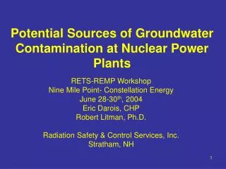
Potential Sources of Groundwater Contamination at Nuclear Power Plants . RETS-REMP Workshop Nine Mile Point- Constellation Energy June 28-30 th , 2004 Eric Darois, CHP Robert Litman, Ph.D. Radiation Safety & Control Services, Inc. Stratham, NH. Experiences. Decommissioning Sites

E N D
Potential Sources of Groundwater Contamination at Nuclear Power Plants RETS-REMP Workshop Nine Mile Point- Constellation Energy June 28-30th, 2004 Eric Darois, CHP Robert Litman, Ph.D. Radiation Safety & Control Services, Inc. Stratham, NH
Experiences • Decommissioning Sites • Connecticut Yankee • Yankee Rowe • Groundwater Dose Contribution to License Termination (LT) Criteria • NRC LT Criteria (10CFR20 Sub E, 10CFR50.82) • 25 mrem/year + ALARA • All Pathways • Resident Farmer Typically Used • GW Contamination Requires Site Specific Dose Modeling (NUREGS)
Hydrogeological Terms • Packer Testing • Hydraulic Conductivity • Pieziometric Surface • Slug Test • Pump Test • Mud and Wash Drilling • Rotosonic Drilling • Glaciolacustrine • Transmissivity • Overburden
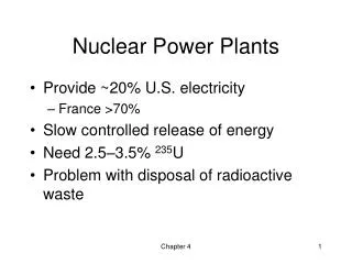
CY Operating History • 582-Mwe Pressurized Water Reactor • Construction Period 1963 - 1967 • Commercial Operation Jan 1, 1968 • Permanently Shut Down December 4, 1996
CY Decommissioning Update • Shutdown 12/96 • Large Components Removed Complete • Final Survey of 400 Wooded Acres Complete • 1st GTCC Canister Located on ISFSI 4/04 • Start Secondary Side Building Removal 5/04 • Start Tank Farm Soil Removal 5/04 • Start RCA Building Removals 7/04 • Complete Fuel Transfer 4/05 • Complete Physical Decommissioning 12/06 • Release Non-ISFSI Areas From License Mid-2007
CY Groundwater Investigation History • Evidence of GW Contamination During Operation • Potable Wells • CTMT Mat Sump – H-3 (~24,000,000 pCi/L) • Confirmed RWST Leak • Possible SFP Leak – Not Confirmed • 1997/1998 – 1st Monitoring Wells Installed • Initial Sampling H-3 and Gamma Only • 143,000 pCi/L H-3 • Formal Hydrogeological Investigation Plan • CT DEP • 2 Phases – Includes Quarterly Sampling • Sr-90 Identified • GW Dose Model Developed for LTP • 2004 – Commitment to DEP • All Contaminants < EPA’s MCLs • 20,000 pCi/L H-3 • 8 pCi/L Sr-90
Bias Detection Case 1: No Bias, Mn-54 March 2002 Data Set
Bias Detection Case 2: + Bias, Tc-99 March 2002 Data Set
Bias Detection Case 3: - Bias, Pu-241 March 2002 Data Set
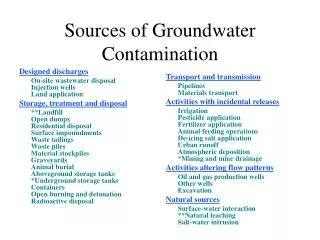
Soil Remediation Plans • Remove Soil from Areas Containing Elevated Contamination to Bedrock – Target Area is Groundwater Source: • Tank Farm Area including Structures • East of Resin Storage Facility • Area between Containment and PAB • Install Well in Area to Monitor for any Residual Contamination
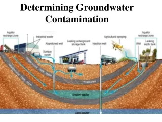
Groundwater Characterization Activities • Conduct Routine Groundwater Monitoring • Review and Document Existing Information - Phase II Plan, Task 1 • Characterize Site-specific Hydrogeologic Conditions – Phase II Plan, Task 2 • Develop Contaminant Fate and Transport Model – Phase II Plan, Task 3
Ongoing Groundwater Monitoring • Continue Quarterly Groundwater Sampling • Decommission Un-needed Wells • Installed Water Level Monitoring System • 33 Monitoring Points, Including Shallow and Deep Zones • Include Surface Water Points at Storm Water Pond, River, and Canal
Phase II Hydrogeologic Work Plan: Task 1 • Conceptual Site Model Elements • Review of Existing Hydrographs/Water Level Data • Assessment of Apparent Contaminant Source Areas • Catalog of Well and Boring Logs • Description and Mapping of Bedrock Features • Hydrogeologic Cross Sections • Preliminary Groundwater Geochemistry Evaluation • Evaluation of Substances of Concern • Preliminary Hydrogeology Evaluation • Measurement Data QC Review • Inventory of Nearby Water Supply Wells
Phase II Hydrogeologic Work Plan: Task 2 • Implement Improved Bedrock Packer Tests • Install Bedrock Monitoring System Based On Packer Test Results • Assess Aquifer Hydraulic Conductivity • Packer Test Measurements • Mat Sump Observations - Long-term Groundwater Extraction • Slug Test Measurements - Localized Measurements • Assess Tidal Influence on Groundwater • Install Additional Monitoring Wells as Needed • Collect Other Supplemental Site-Specific Information to Support Fate and Transport Modeling
3-D Fate and Transport Model: Task 3 • Select Appropriate Simulation Code based on Site Conditions • Preliminary Conceptual Model Elements Include the Following: • Aquifer System Includes Shallow Unconsolidated Formation Overlying Fractured Bedrock • Large variability in unconsolidated system thickness • Bedrock appears to be anisotropic fractured system • Connecticut River is Ultimate Discharge Boundary • Paired wells near the river shore exhibit upward vertical hydraulic gradient • Consistent with the regional concept of the river as a discharge boundary.
CY Lessons Learned • Radionuclides DO NOT Travel Together in Aquifers • Site may have Separate Aquifers • Contamination can Migrate to Depths >150 feet. • Long Term Trends Are Important • Bias Detection • Seasonal Fluctuations • Rain Events • Consider Level Monitoring • Correlate to RainFall • Develop Conceptual Hydrogeologic Site Model • Well Placement • Bedrock Geophysics • Overburden Characteristics
YR Operational History • PWR, Operated from 1960 to 1992 • Initially 485 Mwt, Uprated to 600 Mwt in 1963 • Fuel Clad for ~14 years was Stainless Steel • During the time period 1960-1980 the SFP did not have an interior stainless liner • Significant IX Pit Leak - 1962 • Built adjacent to Sherman Reservoir in the northern Berkshires using a Vapor Containment Design (the BRT) • Ceased Power Operation - 1992
Yankee Rowe Potential Groundwater Contaminating Events • Unlined SFP • IX Pit Leak 1962 • Outside Storage Of Contaminated Materials • Refueling Equipment • Waste • Redistribution of Soil Contamination • RCA Snow Removal • Rain – Storm Drains • Wind • RX Head Impact – Outside Soil Contamination • Underground PVC Drain Pipe Leak
YNPS 1999 Concentration of H-3 in Ground Water Sherman Spring CB-6 CB-2 Grid N CW-7 N (True) CW-8 CW-6 44.5 Deg. CW-10 MW-6 CB-1 CB-9 CW-5 CW-9 MW-5 Monitoring Wells (x are grouted) Site Structures Fence line B-1 CW-1 MW-3 MW-2 CB-10 CW-11 CB-11A CW-3 MW-1 CW-2 CB-12 CB-7 300-3000 pCi/L B-3 CB-8 CW-4 3000-6000 pCi/L CB-3 6000-10000 pCi/L >10,000 pCi/L Approximate Scale 0 200 ft Well H-3 No. pCi/L CB-1 4210 CB-2 1280 CB-3 <MDC CB-6 666 CB-7 <MDC CB-8 <MDC CB-9 4010 CB-10 2330 CB-11A 2030 CB-12 <MDC CW-2 <MDC CW-3 <MDC CW-4 <MDC CW-5 <MDC CW-6 <MDC CW-7 <MDC CW-8 360 CW-10 <MDC CW-11 11600 MW-1 1290 MW-2 11470 MW-5 5610 MW-6 <MDC B-1 2830 Sherman Spring <MDC
Sherman Spring, YNPS Fall 2001 Concentration of H-3 in Ground Water Grid N N (True) 44.5 Deg. CB-6 0 200 ft CB-2 Approximate Scale CW-7 CW-6 CW-8 CW-10 MW-6 CB-1 CB-9 CW-5 CW-9 MW-5 B-1 CW-1 MW-3 MW-2 CB-10 CW-11 CB-11A CW-3 MW-1 CW-2 CB-12 CB-7 CB-8 B-3 CW-4 CB-3
Efforts Beginning in 2003 • Complete groundwater monitoring program established that included: • Suites of radionuclides to be analyzed and relevant locations based on HSA • New locations for wells based on the site geology • Intermediate Depths 60 -200 feet) • Bedrock (some as deep as 300 feet) • Multiple wells at same location for three depths • Frequency for measurements which would adequately monitor changes in the GW
Additional Investigations • More Wells to Further Bound Plume • Step Draw Down Test to Understand Aquifer Connections • Install Network of Level Transducers
Yankee Rowe Lessons Learned • EPA MCLs Selected for Criteria • Prior Investigations Not Rigorous • Little Regulatory Involvement • Involve All Stakeholders • Analyze for Wide Suite of Radionuclides • Include Non-Rad Constituents • Long Term Trends Important
Major Lessons Learned Don’t Wait MCL’s Count