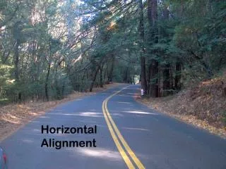
Horizontal Alignment
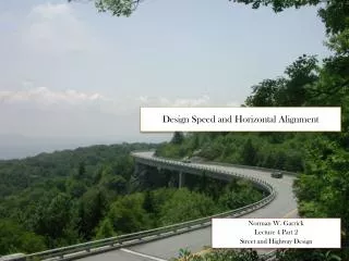
Horizontal Alignment. See: http://www.fhwa.dot.gov/environment/flex/ch05.htm (Chapter 5 from FHWA’s Flexibility in Highway Design). Horizontal Alignment. Design based on appropriate relationship between design speed and curvature and their interaction with side friction and superelevation


Horizontal Alignment
E N D
Presentation Transcript
Horizontal Alignment See: http://www.fhwa.dot.gov/environment/flex/ch05.htm (Chapter 5 from FHWA’s Flexibility in Highway Design)
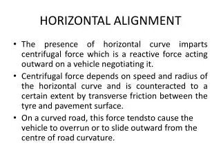
Horizontal Alignment • Design based on appropriate relationship between design speed and curvature and their interaction with side friction and superelevation • Along circular path, inertia causes the vehicle to attempt to continue in a straight line • Superelevation and friction between tire and roadway provides a force to offset the vehicle’s inertia; this force is directed toward the center of curvature (often called centrifugal or centripetal force)
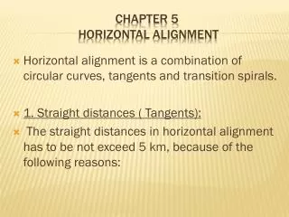
Horizontal Alignment • Tangents • Curves • Transitions Curves require superelevation (next lecture) Reason for super: banking of curve, retard sliding, allow more uniform speed, also allow use of smaller radii curves (less land)
Radius Calculation Rmin = ___V2______ 15(e + f) Where: V = velocity (mph) e = superelevation f = friction (15 = gravity and unit conversion)
Radius Calculation • Rmin related to max. f and max. e allowed • Rmin use max e and max f (defined by AASHTO, DOT, and graphed in Green Book) and design speed • f is a function of speed, roadway surface, weather condition, tire condition, and based on comfort – drivers brake, make sudden lane changes and changes within a lane when acceleration around a curve becomes “uncomfortable” • AASHTO: 0.5 @ 20 mph with new tires and wet pavement to 0.35 @ 60 mph • f decreases as speed increases (less tire/pavement contact)
Max e • Controlled by 4 factors: • Climate conditions (amount of ice and snow) • Terrain (flat, rolling, mountainous) • Frequency of slow moving vehicles who might be influenced by high superelevation rates • Highest in common use = 10%, 12% with no ice and snow on low volume gravel-surfaced roads • 8% is logical maximum to minimized slipping by stopped vehicles
Source: A Policy on Geometric Design of Highways and Streets (The Green Book). Washington, DC. American Association of State Highway and Transportation Officials, 2001 4th Ed.
Radius Calculation (Example) Design radius example: assume a maximum e of 8% and design speed of 60 mph, what is the minimum radius? fmax = 0.12 (from Green Book) Rmin = _____602________________ 15(0.08 + 0.12) Rmin = 1200 feet
Radius Calculation (Example) For emax = 4%? Rmin = _____602________________ 15(0.04 + 0.12) Rmin = 1,500 feet
Curve Types • Simple curves with spirals • Broken Back – two curves same direction (avoid) • Compound curves: multiple curves connected directly together (use with caution) go from large radii to smaller radii and have R(large) < 1.5 R(small) • Reverse curves – two curves, opposite direction (require separation typically for superelevation attainment)
Important Components of Simple Circular Curve See: ftp://165.206.203.34/design/dmanual/02a-01.pdf 1. See handout 2. PC, PI, PT, E, M, and 3. L = 2()R()/360 4. T = R tan (/2) Source: Iowa DOT Design Manual
Sight Distance for Horizontal Curves • Location of object along chord length that blocks line of sight around the curve • m = R(1 – cos [28.65 S]) R Where: m = line of sight S = stopping sight distance R = radius
Sight Distance Example A horizontal curve with R = 800 ft is part of a 2-lane highway with a posted speed limit of 35 mph. What is the minimum distance that a large billboard can be placed from the centerline of the inside lane of the curve without reducing required SSD? Assume p/r =2.5 and a = 11.2 ft/sec2 SSD = 1.47vt + _________v2____ 30(__a___ G) 32.2
Sight Distance Example SSD = 1.47(35 mph)(2.5 sec) + _____(35 mph)2____ = 246 feet 30(__11.2___ 0) 32.2
Sight Distance Example m = R(1 – cos [28.65 S]) R m = 800 (1 – cos [28.65 {246}]) = 9.43 feet 800 (in radians not degrees)
Horizontal Curve Example • Deflection angle of a 4º curve is 55º25’, PC at station 238 + 44.75. Find length of curve,T, and station of PT. • D = 4º • = 55º25’ = 55.417º • D = _5729.58_ R = _5729.58_ = 1,432.4 ft R 4
Horizontal Curve Example • D = 4º • = 55.417º • R = 1,432.4 ft • L = 2R = 2(1,432.4 ft)(55.417º) = 1385.42ft 360 360
Horizontal Curve Example • D = 4º • = 55.417º • R = 1,432.4 ft • L = 1385.42 ft • T = R tan = 1,432.4 ft tan (55.417) = 752.30 ft 2 2
Horizontal Curve Example Stationing goes around horizontal curve. What is station of PT? PC = 238 + 44.75 L = 1385.42 ft = 13 + 85.42 Station at PT = (238 + 44.75) + (13 + 85.42) = 252 + 30.17
Suggested Steps on Horizontal Design • Select tangents, PIs, and general curves make sure you meet minimum radii • Select specific curve radii/spiral and calculate important points (see lab) using formula or table (those needed for design, plans, and lab requirements) • Station alignment (as curves are encountered) • Determine super and runoff for curves and put in table (see next lecture for def.) • Add information to plans