1 / 12

Technological Advancements

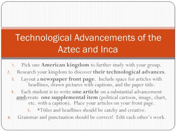
Technological Advancements refer to the development and refinement of tools, systems, devices, and methods that improve human life and solve problems more efficiently. They span across various fields, from communication and medicine to transportation and energy, continually transforming how people interact with the world.

Maheswari7
Download Presentation

Technological Advancements

An Image/Link below is provided (as is) to download presentation Download Policy: Content on the Website is provided to you AS IS for your information and personal use and may not be sold / licensed / shared on other websites without getting consent from its author. Content is provided to you AS IS for your information and personal use only. Download presentation by click this link. While downloading, if for some reason you are not able to download a presentation, the publisher may have deleted the file from their server. During download, if you can't get a presentation, the file might be deleted by the publisher.

E N D

Presentation Transcript


  1. Journal of Mechanical Engineering and Sciences ISSN (Print): 2289-4659; e-ISSN: 2231-8380 Volume 13, Issue 1, pp. 4368-4379, March 2019 © Universiti Malaysia Pahang, Malaysia DOI: https://doi.org/10.15282/jmes.13.1.2019.02.0372 Influence of fins designs, geometries and conditions on the performance of aplate-fin heat exchanger-experimental perspective M. I. N. Ma’arof1, Girma T. Chala2*, Hazran Husain3, Muhammad S. S. Mohamed4 1Department of Mechanical Engineering, INTI International University, Persiaran Perdana BBN, 71800 Nilai, Negeri Sembilan, Malaysia 2Department of Mechanical Engineering, International College of Engineering and Management, P.O. Box 2511, C.P.O Seeb 111, Sultanate of Oman Phone: +96895277384 *Email: girma_tade@yahoo.com 3Faculty of Mechanical Engineering, Universiti Teknologi MARA, Shah Alam 40450 Shah Alam, Selangor Darul Ehsan, Malaysia 4Faculty of Manufacturing Engineering, Universiti Teknikal Malaysia Melaka, Hang Tuah Jaya, 76100 Durian, Tunggal, Melaka, Malaysia. ABSTRACT A fin heat exchanger is a cooling device that involves medium such as fluid to perform heat exchange via convective heat transfer. This study investigates the effects of diverse designs (arrangements of the fins), qualities (the total surface area of the fin) and coating (the surface condition characteristics) of the fin on the degree of heat transfer from the experimental perspective. The fin heat exchangers were fabricated and tested. It was observed that varying the arrangement and condition of the fins could affect the rate of heat transfer. However, varying the quality of the fin by adding perforation to the fin did not have much impact. Nevertheless, the quality aspect of the fin heat exchanger could play a significant role for heat exchangers of larger in scale and dimension. The coating, on the other hand, was observed decreasing the temperature at a much higher margin at all fan speeds. It can be concluded that the design of the fin could highly influence the performance of the fin heat exchanger as opposed to the other two features. For future research, miniature factors or modifications could perhaps further enhance the performance of the fin heat exchangers. Keywords: Heat transfer; fin heat exchanger; convective heat transfer coefficient; efficiency. INTRODUCTION A heat exchanger is a device used for efficient heat transfer from one medium to another [1- 3]. Heat exchanger plays a vital role in various applications, mainly in refrigeration, power generation and air conditioning systems [4-6]. Energy saving is the main concern with regard to heat transfer in this modern era. One of the key steps to address this issue is by increasing the performance of heat exchangers [7]. 4368

  2. Maarof et. al / Journal of Mechanical Engineering and Sciences 13(1) 2019 4368-4379 Over the years, one of the most known designs for the fin heat exchanger was the multi-louvered fin design [8]. A number of experimental studies and numerical simulations for multi-louvered fins were conducted by various researchers [9].A multi-louvered design was inspired by the design arrangement of a windowpane. Rugh et al. [10] studied the design with respect to heat transfer coefficient and friction losses for high-density louvered fin and flat tube heat exchanger (2000fins/m). They found that the louvered fin heat exchanger produced a 25% increase in heat transfer and a 110% increase in pressure drop relative to a plain fin. One of the famous large-scale model experiments was conducted by Lyman et al. [11].Fin pitch and louver angles over a range of Reynolds numbers were tested. They presented a method to evaluate the spatially resolved louver heat transfer coefficients. Additionally, Zhang and Tafti [12]studied the effects of the Reynolds number, fin pitch, louver thickness, and louver angle on flow efficiency in multi-louvered fins. It was observed that flow efficiency was strongly dependent on geometrical parameters, mainly at low Reynolds numbers. These findings were indeed exceptional, capable in providing the inspiration for other researchers. Five experimental factors such as flow depth, ratio of fin pitch and fin thickness, tube pitch, number of louvers, and angle of louver that were believed to be affecting the heat transfer and pressure drop of a heat exchanger with corrugated louvered fins were analyzed by Qi et al. [13]. Their results showed that flow depth, ratio of fin pitch and fin thickness, and the number of louvers significantly influenced the thermal hydraulic performance of the heat exchanger with corrugated louvered fins. These results justify the significance made by varying the characteristics of the fins in regard to the overall performance of the heat exchanger. Baliga et al. [14], in their numerical investigation of the forced convection and heat transfer in triangular plate-fin duct, observed that heat transfer in the thermal entry length was substantial for fine ducts with low fluid speed, which needs to be considered in the design of heat exchangers. Hence, the experiments have proven that the design or arrangement of fin heat transfer is one of the major factors that affect the performance of the fin heat exchanger. The studies made by Sparrow and Ramsey and Sparrow and Kadle were among the first to investigate the heat transfer performance of in-line and staggered wall attached arrays of cylindrical fins, using fins of 2.54 mm in diameter and spaced 5.08 mm apart [15]. Tanda et al. [16],who conducted a study to analyze the pressure drop and heat transfer in a rectangular channel equipped with arrays of diamond-shaped pin fin, proved that the existence of this element has enhanced the heat transfer for equal mass flow rates and equal pumping power. This proves that the quality aspects of the fin heat exchanger, if further investigated, would have an effect on the performance of the fin heat exchangers. Worachest et al. [17] discussed that a porous media in the flow channel intensifies the mixing flow of the fluid and increases the contact surface with the coolant being an effective heat transfer augmentation technique. The study made proposed the ‘‘finite circular fin method (FCFM)” method to analyze the performance of fin-and-tube heat exchangers with plain fin configuration. The heat exchanger was divided into many tiny segments which were: the fully dry, partially wet or fully wet surface conditions. It was observed that the sensible heat transfer performance and the mass transfer performance are insensitive to changes of fin pitch. 4369

  3. Influence of fins designs, geometries and conditions on the performance of a plate-fin heat exchanger- experimental perspective A compact heat exchanger with triangular cross-sectional duct is usually preferred due to its size and easiness to construct it from thin materials with a better mechanical strength [18]. Studies on the three attributes such as design, quality and condition have proven that these attributes play vital roles in the overall performance of the fin heat exchangers. However, not much studies have been carried out to compare all of these attributes against each other. Only major research on the design has been made extensively in-comparison with quality and condition. The objective of this study was, therefore, to investigate the performance of fin heat exchanger as a result of variation in fins designs, qualities and conditions. The key attributes that give the most influence towards the performance of the fin heat exchanger were also identified, which would help give recommendation on the steps or actions undertaken to increase the performance of fin heat exchanger. METHODOLOGY Experimental Setup and Techniques Figure 1 shows the schematic diagram of the test apparatus used. The test apparatus consisted of temperature anemometer, temperature probe, exhaust fan, fan speed controller, fan speed reader, three fin heat exchanger, air duct, stopwatch, wattmeter and heater. Figure 2 shows the fabricated fin heat exchanges that were fitted perfectly in the test box. Figure 1. Experimental setup. The main attributes are fins’ design, quality and condition of the heat exchanger. The term ‘design’ in this study refers to the arrangement or the positional pattern of the fin, which were either perpendicular to the base plate or angled in parallel to the surface of the base 4370

  4. Maarof et. al / Journal of Mechanical Engineering and Sciences 13(1) 2019 4368-4379 plate. Secondly, the term ‘quality’ refers to the total surface area of the fins used for the fin heat exchanger and these included solid as a control or standard benchmark and perforated fins. The term ‘condition’ indicates the fins’ surface condition and this includes the default condition where the surface of the fins was not modified or enhanced in any form. A modified or enhanced fin was coated using an aerosol spray paint as a coating substance. Only one type of coating was used for this study to avoid any variability in terms of heat absorption capability of different colorations. (a) (b) (c) (d) Figure 2. Fin heat exchanger: (a) default, (b) design (angled), (c) perforated and (d) coated (condition). The experimental analysis included three major aspects of the fin heat exchanger: the fin heat exchanger’s design (arrangement of the fin), the fin heat exchanger’s quality (modifications onto the fin), and the fin heat exchanger’s condition (surface integrity of the fin). The attributes of the control are as follow: Control fin heat exchanger (fins are parallel 4371

  5. Influence of fins designs, geometries and conditions on the performance of a plate-fin heat exchanger- experimental perspective at 900 to the surface of the base plate (four in quantity), Perforated fin heat exchanger-12 perforations per fin, Angled fin heat exchanger-fins are arranged 750 parallel to the surface of base plate (total of four rows).All of these designs were generated in 3D model via CATIA prior to the fabrication. The fabrication process consisted of the cutting process via the use of a guillotine sheer. This procedure is the key to the fabrication of the fins for the heat exchanger and needs to be performed in caution to ensure the fins are according to specifications. The specifications of the fin heat exchangers and the base plate are shown in Tables 1 and 2. Table 1. Specification of the fin heat exchanger Types Control Angled No. of fins 9 9 Material Stainless steel sheet metal Dimension (m) 0.1 x 0.1 x 0.01 (length x width x thickness) Weight* (kg) 2.0 2.0 Angle** Parallel to the base plate plate Perforation (m) No No Perforation (quantity) Coating No No Perforated 9 Condition 9 1.98 2.0 300 to the base Parallel to the base plate 0.05 8 for each fin Parallel to the base plate No No No No No Poly (methyl 2- methylpropenoate) *Note: The weight is including the base plate **Note: The angle is measured with respect to the base plate i.e. parallel to the base plate is at 00 angle. Table 2. Specification of the base plate Items Material Dimension (m) Weight (kg) Coating Attachment to the fins Experimental Procedure The control fin heat exchanger was placed into the test duct. The ambient temperature ?∞ was first recorded. The heater power control was set to 75W and the test duct was allowed to reach 80oC. The heater power control was then adjusted to 20W until steady reading obtained. The purpose of this step was to heat the base plate surface of the fin heat exchanger, from which the heated plate surface temperature was recorded as ??. Next, the fan speed was controlled to give speed of 1.0m/s on the thermal anemometer. The reading was then allowed to be stable for 5 minutes prior to taking the reading of ?? again. Subsequently, the fan speed was adjusted to 2.0m/s and then to 2.5m/s. Upon adjustment, the recordings of ?? for each Description Mild steel 0.12 x 0.12 x 0.01 (length x width x thickness) 1.98 No Gas metal arc welding (GMAW) 4372

  6. Maarof et. al / Journal of Mechanical Engineering and Sciences 13(1) 2019 4368-4379 speed were taken. Similar procedures were conducted for the remaining three fin heat exchangers. Convection heat transfer coefficient was calculated as follows: ?̇ ℎ = ? ?(??−?∞) (1) Area of finned surface (for FHX C, FHX D and FHX CD) ? ?=1 ??????? ?????= (∑ ) + ????? (2) ?? Where: ? = number of fins ? = length of fins ? = width of fins Area of finned surface (for FHX Q only) ??????? ?????= (? × ??) − (???2 ) + ????? (3) Where: ? = number of perforation on the fins ? = number of stud on the fins The experiment was carried out in 3 sets of tests. The sets were determined by varying the speed of the exhaust fan. Since the speed of the exhaust fan was varied for each set of the experiment, the type of fluid flow within the confinement of the air duct was also investigated via the Reynolds number. Thus, any form of heat dissipated from the body of the air duct, unstable or varying of power or speed reading for the equipment were considered and discussed in the result and discussion section. The thickness of the sheet metal used for the fin was measured to be 1mm in thickness, which was assumed as negligible. The test was performed in the range of fan speed of 0 m/s to 2.0 m/s (the maximum speed of the exhaust fan), where 0 m/s refers to natural convection while the others for forced convection. The Control test served as a standard for all other tests for comparison. RESULTS AND DISCUSSION Figure 3 shows control and design tests. For all the tests, the Control Test gave the best result in term of the lowest end temperature,Tf. The Control Test showed a gradual decrease in temperature for all runs using variable speeds. The only limitation for the Control Test was the heat transfer coefficient ability of the particular material used at that range or duration of time. The temperature drop for the Control Test was minimal once it reached 500C, showing a gradual removal of heat regardless of forced or natural convection. All tests showed a much 4373

  7. Influence of fins designs, geometries and conditions on the performance of a plate-fin heat exchanger- experimental perspective lower end temperatureas the tests progressed. Comparatively, the Control test was the best fin heat exchanger observed. 80 75 70 Temperature, oC 65 60 CONTROL 55 DESIGN 50 45 40 0 m/s 1 m/s 2 m/s Fan speed Figure 3. Comparison between Control and Design tests. The Design test showed the poorest performance in all types of fin heat exchangers in this study. This result clearly shows that the percentage of difference for Design Test increased with an increase in the fan speed. Thus, it was clear that the main issues with respect to the fin design is the fluid flow. The surface integrity of both Control and Design Test fin heat exchangers were similar; hence, frictional effect due to the surface roughness of the fins was not an issue in the experiment. It was proven that the designs of the fins are highly significant in term of the performance of the fin heat exchanger since it affects the fluid flow. Figure 4 shows comparisons between control and quality tests. The quality issue for fin heat exchanger was expected to be similar in term of performance when compared with the Control Test. The deviation of Tffor Quality Test from Control Test was observed. The result shows that Design Test is relatively similar to that of Control Test; with percentage of deviation in the end temperature was less than 5%. Thus, it can be understood that perforations on the fins do not aid much on the performance of the fin heat exchanger. There wasn’t much difference in term of heat transfer rate when comparing the solid and the perforated fin heat exchangers. It should be noted that the experiment is carried out on a small scaled fin heat exchanger and the perforations made on the fins are also very small. It is proven that the perforations made did not show any positive effect on the performance of the fin heat exchanger. The only positive effect of the perforations was that the fin heat exchanger was slightly lighter than that of the Control Test. Each perforation was only 3.1mm in diameter and the weight reduction per fin was only 0.68 gram per fin. In total there were 9 fins, thus the total of weight reduction for the fin heat exchanger was 6.12 grams. The weight reduction given by the perforation depends on the size and quantity of perforations per fin. Since the deviation from the Control Test was relatively small (less than 5%) in term of performance, the perforated fin heat exchanger could be utilized when the material cost and weight of fin heat exchanger are at concern. For perforated fins, less amount of raw material is required for the mold and the weight could be minimized. 4374

  8. Maarof et. al / Journal of Mechanical Engineering and Sciences 13(1) 2019 4368-4379 Nevertheless, it should be noted that the research was made at a very small scale, and the perforations were almost negligible especially with respect to the surface area of the fins. At a larger scale, if the perforations are made bigger, then this will definitely only lower the performance of the fin heat exchanger since it reduces the surface area of contact for the fluid to remove the heat via convection. Thus, this would give a negative effect on the heat transfer rate. However, at a small scale fin heat exchanger such as in this research, the effect of the perforation on the heat transfer rate of the heat exchanger with perforation on the fin in comparison with the one without is almost negligible. 80 75 70 Temperature, 0C 65 60 CONTROL 55 QUALITY 50 45 40 0 m/s 1 m/s Fan speed 2 m/s Figure 4. Control vs Quality test comparison. Figure 5 shows comparison between control and condition tests. The coatings on the fins were made via aerosol spray paint and the layer made was considerably thin single layer. The coating was allowed for curing under the sun ray for approximately 10 minutes. The results showed that the coating on the fins, instead of conserving heat within the fin, tended to aid in eliminating the heat. Theoretically, coating made on any man-made objects such as pipes or fin heat exchanger serves as an insulation for the object, minimizing the heat loss or emitting heat in the form of thermal radiation. However, not much study in term of convection was carried out for same concept of coating involving thermal convection or convection heat transfer. The coating could also contribute for a better performance of the fin heat exchanger. It was observed that coatings would more be beneficial in regard to protection from corrosion. Thermal insulation provides a means to maintain a gradient of temperature, by providing a region of insulation [19]. From the experiment, it can be argued that the coating provided was not sufficient to act as thermal insulator. Interestingly, although it could be questioned on the thickness of the coating made onto the fins, yet, the results are also evident that the Condition Test showed the highest value of temperature drop for ?0 and ?? i.e. the highest value for delta temperature. 4375

  9. Influence of fins designs, geometries and conditions on the performance of a plate-fin heat exchanger- experimental perspective 80 75 Temperature, 0C 70 65 60 CONTROL 55 CONDITION 50 45 40 0 m/s 1 m/s Fan speed 2 m/s Figure 5. Control Vs Condition test comparison. Figure 6 compares the four tests in terms of temperature change. It was observed that forced convection gave the highest impact on the performance of the coated fin heat exchanger. When it comes to the thickness of the coating, the observation which the Condition Test managed to lose the highest gradient of heat even compared to the control test should be unlikely. The coated fin heat exchanger still managed to lose more heat at the highest fan speed while the Control test showed a decreasing performance. The condition of the fin heat exchanger is very significant on the performance of the heat exchanger. The coated fin heat exchanger gave a performance almost similar to that of the normal (control) heat exchanger. The condition of the fins towards the performance on the fin heat exchanger is highly significant. 12 10 Temperature, 0C 8 6 CONTROL 4 DESIGN 2 QUALITY CONDITION 0 0 m/s 1 m/s Fan speed 2 m/s Figure 6. Control Vs Design Vs Quality Vs Condition in term of Delta T. 4376

  10. Maarof et. al / Journal of Mechanical Engineering and Sciences 13(1) 2019 4368-4379 Comparisons of the Results Overall comparison of the tests is depicted in Figure 7. It can be seen that designs of the fins had significant influence on the fin heat exchanger since it clearly impacted the performance towards heat transfer capability. The main concern on fin designs is its effect on the behavior of the fluid flow. Quality of the fins is confined by the reality of the surface area of contact with the fluid. The bigger surface area of contact with the fluid, the better would be the performance of the fin heat exchanger in dissipating heat. Therefore, the main concern with regard to the quality of the fins is achieving the biggest surface area possible for the fins. Condition of fins could give unexpected result on the performance of fin heat exchanger. The coating made onto the fins seems to aid in decreasing the temperature at a much higher margin at all fan speeds. The main concern with respect to this matter is the thickness of the coating on the fins. Variable thickness could give variable results. It should be noted that the best performance from the experiment was found with Control Test of the basic design of the fin heat exchanger. 80 75 Temperature 0C 70 65 CONTROL 60 DESIGN 55 QUALITY 50 CONDITION 45 40 0 m/s 1 m/s 2 m/s Fan speed Figure 7. Overall comparison of the tests. CONCLUSION The performances of the fin heat exchanger with respect to different attributes including designs, qualities and conditions of the fin were investigated experimentally. The fin heat exchangers were designed and fabricated for analysis purpose. It was observed that the main attributes that highly influence the performance of the fin heat exchanger was the design of the fin. This is because the design of the fins would influence the fluid flow that serves as the medium of convective heat transfer as it passes along the heat exchanger. Performance variation was minimal and insignificant when the quality of the fin was changed. 4377

  11. Influence of fins designs, geometries and conditions on the performance of a plate-fin heat exchanger- experimental perspective Nevertheless, the quality aspect of the fin heat exchanger could play an enhanced role on heat exchanger of larger in scale and dimension. The coating on the fins was also observed decreasing the temperature at a much higher margin at all fan speeds. For future research, miniature factors or modifications that may include the concepts of nozzle effect to increase the end velocity of the fluid, testing of different thickness of the coating and making fin a solid in integrity to increase its area could perhaps give a big improvement on the performance of the fin heat exchangers. REFERENCES [1] Knissel J, Peußner D. Energy efficient heat exchanger for ventilation systems. Energy and Buildings 2018;159:246-253. [2] Pradeep GV, Narasimha, KR. Thermal performance of a vertical closed loop pulsating heat pipe and analysis using dimensionless numbers. Journal of Mechanical Engineering and Sciences 2017;11(4):3240-3255. [3] Abdullah A, Mohamad IS, Hashim AY, Abdullah N, Poh BW, Isa M, Zainal AS. Thermal conductivity and viscosity of deionised water and ethylene glycol-based nanofluids. Journal of Mechanical Engineering and Sciences 2016;10:2249-2261. [4] Ghani S, Gamaledin SMA, Rashwan MM, Atieh MA. Experimental investigation of double-pipe heat exchangers in air conditioning applications. Energy and Buildings 2018;158:801-811. [5] Chala GT, Sulaiman SA, Japper-Jaafar A, Kamil WA. Investigation of convective heat transfer coefficient and initial temperature of waxy crude oil on the formation of voids. International Journal of Automotive & Mechanical Engineering 2016;13(3):3754-3762. [6] Haque ME, Bakar RA, Kadirgama K, Noor MM, Shakaib M. Performance of a domestic refrigerator using nanoparticles-based polyolester oil lubricant.Journal of Mechanical Engineering and Sciences 2016;10(1):1778-1791. [7] Sahiti N. Interrelation between pin length and heat exchanger performance.Applied Thermal Engineering 2015;91:946-952. [8] Yu E, Joshi Y. Heat transfer enhancement from enclosed discrete components using pin–fin heat sinks. International Journal of Heat and Mass Transfer 2002;45(25):4957-4966. [9] Dong J, Chen J, Chen Z, Zhang W, Zhou Y. Heat transfer and pressure drop correlations for the multi-louvered fin compact heat exchangers. Energy Conversion and Management 2007;48(5):1506-1515. [10] Rugh JP, Pearson JT, Ramadhyani S. Study of a very compact heat exchanger used for passenger compartment heating in automobiles. Presented in 28th National Heat Transfer Conference and Exhibition, San Diego, CA, USA, 09-12/1992:15-24. [11] Lyman AC, Stephan RA, Thole KA, Zhang LW, Memory SB. Scaling of heat transfer coefficients along louvered fins. Experimental Thermal and Fluid Science 2002;26(5):547-563. [12] Zhang X, Tafti DK. Flow efficiency in multi-louvered fins. International Journal of Heat and Mass Transfer 2003;46(10):1737-1750. 4378

  12. Maarof et. al / Journal of Mechanical Engineering and Sciences 13(1) 2019 4368-4379 [13] Qi ZG, Chen JP, Chen ZJ. Parametric study on the performance of a heat exchanger with corrugated louvered fins. Applied thermal engineering 2007; 27(2-3):539-544. Baliga BR, Azrak RR. Laminar fully developed flow and heat transfer in triangular plate-fin ducts. Journal of heat transfer 1986; 108(1):24-32. Sparrow EM, Ramsey JW. Heat transfer and pressure drop for a staggered wall- attached array of cylinders with tip clearance. International Journal of Heat and Mass Transfer 1987;21(11):1369-1378. Tanda G. Heat transfer and pressure drop in a rectangular channel with diamond- shaped elements. International Journal of Heat and Mass Transfer 2001;44(18):3529- 3541. Pirompugd W, Wang CC, Wongwises S. Finite circular fin method for heat and mass transfer characteristics for plain fin-and-tube heat exchangers under fully and partially wet surface conditions. International Journal of Heat and Mass Transfer 2007;50(3-4):552-565. Zhang LZ. Laminar flow and heat transfer in plate-fin triangular ducts in thermally developing entry region. International Journal of Heat and Mass Transfer 2007;50(7- 8):1637-1640. Huang J, Yu J, Yang H. Effects of key factors on the heat insulation performance of a hollow block ventilated wall. Applied Energy 2018;15(232):409-23. [14] [15] [16] [17] [18] [19] 4379

More Related