Download

1 / 45
450 likes | 475 Views
Design For Assembly<br><br>https://www.7pcb.com/Upload_file/DFA_Guidelines.pdf<br><br>The purpose of this Design for Assembly (DFA) guide is to assist Bitteleu2019s customers in designing printed circuit boards (PCBs) that can be assembled in an efficient and cost-effective manner. <br><br>Design For Assembly<br>

E N D
Rigid PCB Design For Assembly Guide Updated: January 10th, 2023 ©Bittele Electronics Inc.
BITTELE ELECTRONICS DFAGUIDE FOR PCBDESIGNERS PAGE 1 OF 44 Table of C Table of Contents ontents List of Figures and Tables ...................................................................................................................................... 4 1.0 – Introduction ................................................................................................................................................. 5 1.1 – Definition of DFA ...................................................................................................................................... 5 1.2 – Scope ........................................................................................................................................................ 5 2.0 – Principles of DFA for PCBs ............................................................................................................................ 1 2.1 – Reduction & Combination ........................................................................................................................ 1 2.1.1 – Reduction (Total Part Count) ............................................................................................................ 1 2.1.2 – Combination (Total BOM Lines) ........................................................................................................ 1 2.2 – Standardization ........................................................................................................................................ 2 2.2.1 – Parts & Vendors ................................................................................................................................ 2 2.2.2 – Component Packages ........................................................................................................................ 2 2.3 – Minimization of Risk ................................................................................................................................. 2 2.3.1 – Reliability ........................................................................................................................................... 3 2.3.2 – Fragility .............................................................................................................................................. 3 2.3.2 – Heavy and Unwieldy Parts ................................................................................................................ 3 2.4 – Simplification ........................................................................................................................................... 3 2.4.1 – Complex Parts ................................................................................................................................... 4 2.4.2 – Complex Processes ............................................................................................................................ 4 2.5 – Clarity ....................................................................................................................................................... 6 2.5.1 – File Clarity & Files Required for PCB Assembly ................................................................................. 6 2.5.2 – Design Clarity .................................................................................................................................... 9 3.0 –Understanding Bittele’s Assembly Capabilities .......................................................................................... 10 3.1 – Orientation ............................................................................................................................................. 10 3.1.1 – Preferred Markings ......................................................................................................................... 10 3.1.2 – Consistency ..................................................................................................................................... 12 3.1.3 – Zero Orientation .............................................................................................................................. 12 3.1.4 – Wave Soldering ............................................................................................................................... 13 3.2 – Spacing ................................................................................................................................................... 13 3.2.1 – Part-to-Part Spacing ........................................................................................................................ 13 3.2.2 – Part-to-Edge Spacing ....................................................................................................................... 14 3.2.3 – Part-to-Hole Spacing ....................................................................................................................... 15 Document Contents ©Bittele Electronics 2021
BITTELE ELECTRONICS DFAGUIDE FOR PCBDESIGNERS PAGE 2 OF 44 3.3 – Sizing ...................................................................................................................................................... 17 3.3.1 – Pad and Hole Sizes .......................................................................................................................... 17 3.3.2 – Package Sizes................................................................................................................................... 18 3.3.3 – Pitch ................................................................................................................................................ 19 3.4 – Equipment Capabilities .......................................................................................................................... 20 3.4.1 – Tolerances ....................................................................................................................................... 20 3.4.2 – Production Rates ............................................................................................................................. 21 3.5 – Standards & Certifications ..................................................................................................................... 22 3.5.1 - IPC-A-610 ......................................................................................................................................... 22 3.5.2 – SMTA ............................................................................................................................................... 22 3.5.3 – ISO-9001:2008 ................................................................................................................................. 23 3.6 – Reflow Soldering .................................................................................................................................... 23 3.6.1 – When to Reflow .............................................................................................................................. 23 3.6.2 – Heat Profiles .................................................................................................................................... 23 3.6.3 – Reflow Oven Specifications ............................................................................................................. 24 3.7 – Wave Soldering ...................................................................................................................................... 24 3.7.1 – When to Wave Solder ..................................................................................................................... 24 3.7.2 – Heat Profiles .................................................................................................................................... 25 3.7.3 – Orientation & Shadowing................................................................................................................ 25 3.7.4 – Pad Shapes ...................................................................................................................................... 26 3.8 – Manual Soldering ................................................................................................................................... 26 3.8.1 – When to Manually Solder ............................................................................................................... 26 3.8.2 – Manual Soldering Restrictions ........................................................................................................ 27 3.9 – Special Assembly Requirements ............................................................................................................ 27 3.9.1 – Mechanical Component Assembly .................................................................................................. 27 3.9.2 – Adhesives ........................................................................................................................................ 28 3.9.3 – Pressfit Parts ................................................................................................................................... 29 3.9.4 – Wire Bonding .................................................................................................................................. 29 3.9.5 – Wire Harness ................................................................................................................................... 29 3.9.6 – Enclosure Assembly ........................................................................................................................ 30 3.9.7 – Conformal Coating .......................................................................................................................... 30 3.9.8 – IC Programming............................................................................................................................... 30 3.9.9 – Serialization ..................................................................................................................................... 31 Document Contents ©Bittele Electronics 2021
BITTELE ELECTRONICS DFAGUIDE FOR PCBDESIGNERS PAGE 3 OF 44 3.9.10 – Flux and Solder Types ................................................................................................................... 31 3.10 – Common Assembly Issues .................................................................................................................... 32 3.10.1 – Tombstones & Open Circuits ........................................................................................................ 32 3.10.2 – Tin Whiskers .................................................................................................................................. 33 3.10.3 – Solder Bridges ............................................................................................................................... 33 3.10.4 – Solder Balls .................................................................................................................................... 34 3.10.5 – Joint Voids ..................................................................................................................................... 35 3.11 – Testing Methods – Design for Testing ................................................................................................. 35 3.11.1 – Automated Optical Inspection (AOI) ............................................................................................. 35 3.11.2 – X-Ray Inspection ............................................................................................................................ 36 3.11.3 – Functional Circuit Testing (FCT) .................................................................................................... 37 4.0 - Conclusion ................................................................................................................................................... 38 5.0 – References ................................................................................................................................................. 39 Document Contents ©Bittele Electronics 2021
BITTELE ELECTRONICS DFAGUIDE FOR PCBDESIGNERS PAGE 4 OF 44 List of Figures and Tables List of Figures and Tables Figure 1 - RF Filter in a Single 0402 Package ......................................................................................................... 1 Figure 2 – Via-In-Pad Fanout (Left) and Dog-Bone Fanout (Right) ....................................................................... 5 Figure 3 - Bittele's Sample BOM ........................................................................................................................... 6 Figure 4 - Sample Centroid File ............................................................................................................................. 7 Figure 5 - Mechanical Gerber Layer ...................................................................................................................... 8 Figure 6 - Assembly Drawing Showing Component Placements .......................................................................... 8 Figure 7 - Clear (Recommended) Orientation Markings ..................................................................................... 11 Figure 8 - Unclear (NOT Recommended) Orientation Markings ........................................................................ 12 Figure 9 - Example of Consistent Orientation ..................................................................................................... 12 Figure 10 - Part-to-Board Outline Spacing .......................................................................................................... 14 Figure 11 - Part-to-Hole Wall and Part-to-Annular Ring Spacing ........................................................................ 15 Figure 12 - Bad Idea - Via Placed Between SMT Pads ......................................................................................... 16 Figure 13 - Via Routing For QFN & QFP Packages - Preferred (left) & Acceptable (right) .................................. 16 Figure 14 - Minimum Ratio (C1 - Left) & Larger Ratio (C2 - Right) – Both Acceptable ....................................... 17 Figure 15 - THT Hole-to-Lead Sizing – IPC-2222A ............................................................................................... 18 Figure 16 - Annular Ring Illustration ................................................................................................................... 18 Figure 17 - Bow & Twist on a Centrally-Placed BGA (Exaggerated for Clarity) ................................................... 19 Figure 18 - BGA Packages Placed "On Top Of" One Another .............................................................................. 19 Figure 19 - Reflow Heat Cycle ............................................................................................................................. 24 Figure 20 - Poor Wave Soldering Orientation (Left) & Good Wave Soldering Orientation (Right) ..................... 25 Figure 21 - Thieving Pads on a SOIC-14 Package ................................................................................................ 26 Figure 22 – Some of Bittele's Direct-Chip Programming Equipment .................................................................. 31 Figure 23 - Example of a Tombstone Defect (left) and an Open Circuit Defect (Right) ...................................... 32 Figure 24 - Reactions on Solder Joint for Bent Lead or Flat Pack ....................................................................... 33 Figure 25 - Solder Bridge on a SO-Style IC Package ............................................................................................ 34 Figure 26 - Solder Ball on a Passive Package ...................................................................................................... 34 Figure 27 – X-Ray Image of Solder Joint Voids .................................................................................................... 35 Figure 28 - X-Ray Image of an Assembled BGA Package ..................................................................................... 36 Figure 29 - Bittele Test Engineer Performing FCT on an Assembled Board ........................................................ 37 Table 1 - Part-to-Part Spacing Matrix (All Dimensions in mil / thou).................................................................. 14 Table 2 - Annular Ring Size by Copper Weight.................................................................................................... 18 Table 3 - AOI Thresholds ..................................................................................................................................... 36 Document Contents ©Bittele Electronics 2021
BITTELE ELECTRONICS DFAGUIDE FOR PCBDESIGNERS PAGE 5 OF 44 1.0 1.0 – – Introduction Introduction The purpose of this Design for Assembly (DFA) guide is to assist Bittele’s customers in designing printed circuit boards (PCBs) that can be assembled in an efficient and cost-effective manner. The following sections will define the various tolerances, rules, and procedures to which Bittele adheres during the PCB assembly process. 1.1 – Definition of DFA Design for Assembly refers to a specific method of design that takes into account not only the functionality of a finished product, but also the cost and efficiency of the assembly process for that product. Many design decisions can have an immense impact on these factors of efficiency and cost during the assembly process, which will in turn affect the overall quality and reliability of the finished product. For PCB projects in particular, a clear understanding of DFA will help to reduce the costs of parts procurement and component placement, which normally account for a majority of the total price in full turnkey service. These techniques can act to minimize a project’s overall lead time and protect against assembly issues that would otherwise necessitate design revision or time-consuming rework. The principles of DFA are closely related to those of DFM (Design for Manufacturing), and both of these methods should be carefully considered in order to create the best possible product. Bittele Electronics also provides a DFM Guidelines document in an effort to provide clients with a complete picture of their options in PCB Fabrication as well as PCB Assembly. 1.2 – Scope These DFA guidelines will proceed with a clear and comprehensive discussion around the strategies of DFA as they relate specifically to PCB projects. Though many of these strategies apply in a general sense to all areas of design, this discussion will offer definitive examples and illustrations in the realm of PCB assembly specifically. A brief outline of these strategies is given below: ▪ ▪ ▪ ▪ ▪ ▪ Reduction & Combination Standardization Minimization of Risk Simplification Clarity Understanding Assembler Capabilities* Each of these six points are extremely important in the overall picture of DFA, but the final strategy of understanding assembler capabilities is the most explicit and multi-faceted; this point also tends to affect a designer’s ability to achieve the remaining five strategies. With this in mind, a longer section of this document has been dedicated to the specific PCB assembly capabilities of Bittele Electronics in the following areas: ▪ ▪ ▪ ▪ ▪ ▪ ▪ ▪ ▪ ▪ Orientation Spacing Sizing Standards & Certifications Reflow Soldering Wave Soldering Manual Soldering Special Assembly Requirements Common Assembly Issues Testing Methods Document Contents ©Bittele Electronics 2021
BITTELE ELECTRONICS DFAGUIDE FOR PCBDESIGNERS PAGE 1 OF 44 2.0 2.0 – – Principles of DFA Principles of DFA for PCBs for PCBs 2.1 – Reduction & Combination 2.1.1 – Reduction (Total Part Count) One of the most intuitive methods for reducing cost and improving ease of assembly for a PCB project is to decrease the total number of parts to be populated on a board. Not only will this decrease the total cost for the project’s Bill of Materials (BOM), it will also reduce the number of passes required for Bittele’s Pick & Place machines to assemble the board during production. Of course, each piece of a particular design has its own specific function, but as a design moves into high levels of production it becomes increasingly important to balance the necessity of those functions against DFA concerns. It might be worth compromising on a few ancillary features for a more stable and cost-effective product, but even in the case where every component is essential, it is still possible to reduce the total part count through part combination. 2.1.2 – Combination (Total BOM Lines) When a PCB design moves from prototype into production, it is crucial to look for part combination opportunities. Passive components are often available in array form, with multiple resistors or capacitors combined into a single package. In some cases, a certain circuit element can be replaced by a single part; for example, the image below shows a low-pass RF filter in a single 0402 package. Figure 1 - RF Filter in a Single 0402 Package Combination can also be achieved through generalization of passive parts with non-critical values; for example, parts such as decoupling capacitors can often be matched with other common parts in the design to reduce the total number of BOM lines for the project. This strategy might not reduce the total part count for the project, but it will reduce the necessary number of reel changes during assembly, and thereby decrease both the cost and time requirements of the process. Bittele’s PCB Assembly quotes take this factor into consideration, so these reductions in cost and lead time will be passed along to the client. Document Contents ©Bittele Electronics 2021
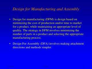
BITTELE ELECTRONICS DFAGUIDE FOR PCBDESIGNERS PAGE 2 OF 44 2.2 – Standardization Any new PCB design brings with it a degree of uncertainty; even the most experienced engineer will have a hard time predicting every possible complication that could occur along the way. The key in standardization is to keep the level of uncertainty to a minimum by utilizing parts and processes that have worked in the past. 2.2.1 – Parts & Vendors In the realm of PCB assembly, the components themselves are perhaps the most easily controlled sources of uncertainty in a project. Certainly this is not to say that a PCB designer should never list new, cutting-edge parts in their BOM, but such parts surely deserve extra attention both during the design phase and during PCB assembly. As such, Bittele would recommend that any new components in a design be balanced with tested and stable parts from previous designs. The source of each component should also be carefully considered, since an unreliable source introduces greater potential for delay, misinformation, and even fake parts. Bittele provides two effective solutions in this regard: a professional parts procurement service available at zero component price markup, and a stock of reliable passives offered entirely free of charge. 2.2.2 – Component Packages Simply put: the greater the number of unique component packages in a given BOM, the greater the time requirement for Bittele’s DFA check prior to PCB assembly. The DFA check includes a comparison of each land pattern in the PCB layout against the datasheet footprint for each part in the BOM. This comparison necessarily becomes more onerous as the number of unique packages is increased. If the DFA check process does discover footprint-to-land pattern mismatches, the necessary design revisions will also be more quickly completed when fewer unique land patterns exist across the design. During the assembly process itself, different types of component packages often come with their own unique demands and process controls. As such, a reduction in the number of unique package types will simplify the PCB assembly process as a whole, thereby reducing both lead time and potential for error. Specific process requirements for certain component packages are discussed in Section 2.3.1 and Section 2.3.2, below. 2.3 – Minimization of Risk Similar to the uncertainty mentioned in the previous section (Section 2.2), each PCB project carries with it some necessary risk; in fact, these two concepts are closely related to one another. A primary strategy in the minimization of risk is the minimization of uncertainty through standardization, but even well-known processes involve some degree of risk. In order to produce the best possible product, it is essential for both the PCB designer and the PCB assembler to understand and account for the specific risks involved in each individual project. Document Contents ©Bittele Electronics 2021
BITTELE ELECTRONICS DFAGUIDE FOR PCBDESIGNERS PAGE 3 OF 44 2.3.1 – Reliability Parts chosen for PCB assembly should come from time-tested reliable manufacturers to ensure their accuracy and stability, as well as reliable delivery. Special attention should be paid to the current market status of each part as well; if a part is marked End-of-Life or Obsolete by the manufacturer, it is normally best to look for a replacement right away. Such deprecated parts may still be available for some time, but keeping them in the design any longer than absolutely necessary will likely cause delays for future runs. Bittele Electronics boasts a professional parts procurement team that will work with clients to ensure all parts come from reputable sources, and that any stock or market status issues are resolved quickly and easily. 2.3.2 – Fragility The physical properties of the parts in a particular design will impact the overall risk of production loss for the assembly process itself. Bittele Electronics always takes this into account, and ensures that each client’s order is filled in its entirety, regardless of potential complications during assembly. Still though, a clear awareness of the more risky parts will increase the overall efficiency of the process by minimizing the need for re-work or re-make after the fact. Bittele can handle assembly for passive packages down to 0201 imperial, but production loss will likely be relatively high for these types of parts. This results mainly in additional assembly cost where 0201 passives are involved, to cover for the careful handling required as well as the additional stock necessary to protect against production loss. It is recommended to use 0603 or larger passive packages as often as possible to minimize both the price and production loss for each PCB assembly project 2.3.2 – Heavy and Unwieldy Parts The concern with particularly large or heavy parts is mainly in shipping and handling costs. Parts such as transformers or power resistors will incur much higher shipping costs for their initial transportation to Bittele’s assembly facilities, as well as the final shipment of the assembled PCBs to the client. It is not always possible to eliminate such parts from a design, but it is important to be aware of these potential sources of extra cost well in advance. Parts requiring manual assembly will decrease the efficiency of a mainly-automated PCB assembly process. Through-hole parts on a majority surface-mount design or mounting hardware for final assembly will require additional attention from Bittele’s staff, which drives up both the cost and the lead time of a project. 2.4 – Simplification The concept of simplification in PCB Assembly is tied in closely with minimization of risk (see Section 2.3). The difference for this section is that the impact on the assembly process comes from the complexity of the parts or processes involved, rather than their physical properties or market status. Some level of risk is unavoidable in any PCB project, but complexity can more often be reduced or even eliminated through savvy design techniques. This is not always the case, and sometimes complex parts or processes are indeed required, but simplification wherever possible will help to bring down the overall cost and lead time of any PCB project. Document Contents ©Bittele Electronics 2021
BITTELE ELECTRONICS DFAGUIDE FOR PCBDESIGNERS PAGE 4 OF 44 2.4.1 – Complex Parts Complex parts are sometimes required for a complex product, but it is important to understand the additional considerations that must be made for these components in order to better plan and budget for a product during the design phase. As such, this subsection will proceed with a list of the more complex parts that Bittele can install, followed by a brief description of their requisite assembly considerations. BGA, LGA, QFN, CSP, & FLIP-CHIP The above four terms all describe parts with no external leads, meaning Bittele must use X-Ray inspection during the final quality check of the assembled PCBs. This verification process incurs some extra PCB Assembly cost compared to QFP-style packages. Rework is also much more difficult for these types of parts, which makes the entire assembly process much less forgiving. The very fine-pitch versions of these packages will sometimes require complex processes as well, such as via-in-pad filling described below in Section 2.4.2. POP (Part-on-Part) POP technology allows certain components to be stacked on top of one another during the PCB assembly process; for example, some advanced processors will have their memory modules mounted directly on top of the main processor package. This technology offers key advantages in miniaturization for many high-density designs, but also requires special consideration during PCB assembly, including multiple placement and reflow cycles. These additional considerations can drive up both cost and lead time for a PCB assembly project. 2.4.2 – Complex Processes Complex processes are sometimes required for certain complex parts, as mentioned in the previous section, but might also come into play even for standard PCB designs. A PCB designer must observe certain physical requirements depending upon the environmental stresses that will be placed upon their finished product, and some of these requirements can be satisfied through complex PCB assembly processes. This subsection aims to give designers an idea of the PCB assembly considerations required by some of the more common complex processes offered by Bittele Electronics. Via In Pad This process is sometimes required for extremely fine-pitch parts such as µBGA packages when there may not be enough room between pads for a standard “dog-bone” style fan-out – pictures are included below for both of these fan-out methods. Vias in component pads will create a risk of leaking tin during the reflow process, which can cause shorts or corrupt pads. In order to stabilize the assembly process, vias in surface mount pads must be filled with epoxy, which requires additional cost and lead time. Bittele can confidently handle via-in-pad designs, but would recommend avoiding this requirement if possible to simplify the PCB assembly process. Document Contents ©Bittele Electronics 2021
BITTELE ELECTRONICS DFAGUIDE FOR PCBDESIGNERS PAGE 5 OF 44 Figure 2 – Via-In-Pad Fanout (Left) and Dog-Bone Fanout (Right) Wire Bonding Bittele offers a selective soft gold surface finish option, which can be applied to specific areas or specific pads on a board during the PCB Fabrication process to allow for wire bonding. This allows for a stronger welded joint on the pad in question, which offers increased durability for leads soldered directly to the PCB. This process requires a mask drawing to specify the regions for soft gold finish, as well as additional documentation to describe the wire bonding procedure, and might not be viable for volume orders. Generally, it is more cost- and time-effective to use connectors and terminated cables for interconnection, but wire bonding might be necessary for size-restricted designs that are unable to incorporate these larger parts. Wire Harness Assembly Bittele is focused on board-level PCB Assembly services, and will only offer wire assembly on a case-by-case basis. This requirement should be mentioned during the quoting stage of the project so that the associated design drawings can be analyzed in advance by Bittele’s engineering team. Wire or cable assembly will most often require manual attention, which can cause a significant increase in both cost and lead time for a project. Rather than deal with wire harness assembly, some clients choose to combine modular design components onto a single PCB or to use special features in PCB fabrication such as gold fingers or rigid-flex interconnection. Conformal Coating For PCBs that will be used in damp, humid, dusty, or other harsh environments, a special process known as conformal coating is often required. Through this process, Bittele will cover the assembled PCB in a layer of non-conductive, protective material such as silicon, acrylic, urethane, or paraxylene. Once this coating is cured onto the board, it will increase the overall durability of the product while also protecting it from outside contaminants. Clients should submit a masking drawing along with standard design files to stipulate any areas of the board that should not be subjected to the coating, such as connectors that will need to be accessed at a later time. The conformal coating process does require additional time and cost after PCB assembly, and Bittele also requires that functional testing (see Section 3.10) be performed on assembled PCBs prior to coating. Once the coating has been applied, the boards are fully sealed, and rework can no longer be performed. Document Contents ©Bittele Electronics 2021
BITTELE ELECTRONICS DFAGUIDE FOR PCBDESIGNERS PAGE 6 OF 44 2.5 – Clarity 2.5.1 – File Clarity & Files Required for PCB Assembly Inconsistent or unclear data in design files will prompt additional questions and introduce confusion prior to the PCB assembly process, potentially increasing the overall project lead time. Most commonly, these types of issues arise when information in one document disagrees with information in another, so a thorough check that all design revisions are reflected on all documentation can pre-empt many questions during the assembly process. Aside from maintaining consistency between design files, there are a few general strategies for file clarity in each of the four main types of design files Bittele requires: BOM Clarity Many CAD programs for PCB layout offer the option to automatically generate a BOM based on reference designators, footprints, and component values specified during the schematic design phase. These options can be used to save on time and minimize common errors such as mis-matches between quantity and number of reference designators. That being said, a manual review of the software-generated BOM is still essential to ensure maximum clarity. Some of the most common BOM issues that Bittele has noticed in the past are listed below: - - - Incomplete, ambiguous, inaccurate, or missing part numbers Quantity to reference designator mis-matches Part number to description mis-matches Some manual work might be required on the software generated BOM in order to bring it into a clear and concise format, but this will save time and pre-empt mistakes later in the process. At the very least, a BOM should include complete information for Quantity, Reference Designators, and Part Number on each line; including Manufacturer, Description, and additional instructions will further protect against potential delays or mistakes. Find Bittele’s sample BOM here. Figure 3 - Bittele's Sample BOM Document Contents ©Bittele Electronics 2021
BITTELE ELECTRONICS DFAGUIDE FOR PCBDESIGNERS PAGE 7 OF 44 Centroid Clarity Clarity in the Centroid file – also known as XY-Coordinate or Pick & Place file – is extremely important, since this data will be directly used to program Bittele’s Pick and Place machines for automatic part placement. Centroid data is generated directly by the CAD software used for PCB layout, but this does not make it immune to inaccuracy or ambiguity. The following issues are the most common for Centroid data: - - - Disagreement with the BOM, usually due to project updates not reflected in one document Missing parts, usually due to errors in the CAD software Inaccurate coordinates, usually due to a Gerber file update without generating a new Centroid A sample Centroid file is shown below: Figure 4 - Sample Centroid File Gerber File Clarity Gerber files are used mainly in the PCB Fabrication process –see Bittele’s DFM Guidelines document for more detailed information about Gerber files – but they do also play a role in the PCB Assembly process. The first thing to note about Gerber files and their role in PCB Assembly is the Silkscreen layer. This layer shows reference designators for specific components beside their associated land patterns. During Bittele’s initial DFA check sequence, these reference designators are compared with those in the BOM and Centroid files to ensure that any errors in one file are caught early and brought to the client’s attention. The silkscreen layer also contains markings for the orientation of polarized components, which can help to avoid questions and potential issues during assembly – more on part orientation in Section 3.1. Some HDI boards do not have enough room between components for a silkscreen layer, and some clients simply do not want to include silkscreen markings on the finished board for aesthetic reasons. In this case, Bittele will require assembly drawings or mechanical Gerber layers to act as substitute for the silkscreen layers. Mechanical layers in the Gerber set can include specific instructions for the mounting of certain components, and many designers include additional notes in these layers for standard and special requirements. For example: a particular part might require unconventional mounting orientation, or perhaps the PCB in question requires the use of water-soluble flux rather than standard no-clean flux. Including these notes in the Gerber files will ensure that Bittele’s engineering team makes note of them early in the manufacturing process and plans accordingly. See the picture below for an example of a mechanical Gerber file. Document Contents ©Bittele Electronics 2021
BITTELE ELECTRONICS DFAGUIDE FOR PCBDESIGNERS PAGE 8 OF 44 Figure 5 - Mechanical Gerber Layer Issues around Gerber file clarity in PCB Assembly are often a result of design revisions that are not reflected across all files, causing a discrepancy between the Gerbers and the BOM, Centroid, or Assembly Drawing. Notes are sometimes copied from a previous design to save time, but design differences are often overlooked in this case; it is recommended to use an empty notes template and fill it for each project individually to minimize these sorts of errors. Assembly Drawing Clarity Assembly drawings are a supplementary file, used to offer additional clarity on the required PCB assembly and to describe in detail any special requirements for the project in question. Most PCB Layout software suites include an option for generating assembly drawings, which will generally output to PDF both a top-down and a bottom-up view of the board, as below: Figure 6 – Top-Down Assembly Drawing Showing Component Placements Document Contents ©Bittele Electronics 2021
BITTELE ELECTRONICS DFAGUIDE FOR PCBDESIGNERS PAGE 9 OF 44 A basic assembly drawing, such as the one shown above, can help to clarify placements and DNI (Do Not Install) parts, but it is sometimes necessary to provide more information to clarify special requirements. Processes such as wire assembly, as well as specifications for temperature tolerances, flux and solder types, or manual assembly parts, should be included in the assembly drawing. These types of specifications can be added on a separate page of the PDF document or simply included in the margins of the drawings themselves. Bittele Electronics recommends including at least a basic assembly drawing with any PCB Assembly project submission. As a general rule: the more information that is included on the drawing, the fewer the number of questions asked during assembly. 2.5.2 – Design Clarity Clarity must be observed not only with respect to the contents of design files provided to Bittele, but also the PCB design itself. Bittele often needs to pause the assembly process to clarify ambiguities in the design, sometimes causing a delay to the overall project timelines when a clear design could have resolved these questions before they ever arose. Taking the extra time during the design phase of a project to ensure orientations are marked as clearly as possible will reduce the potential for delays during PCB Assembly. Assembly side is another potential source of ambiguity; though it is mostly handled by the Centroid file for automatic assembly parts, the safest method is simply to stick with single-sided PCB designs as often as possible. For manual assembly parts, it is best to note orientation and assembly side clearly in both the BOM and the Assembly Drawing. In general, a detailed silkscreen and mechanical layers in the Gerber files will greatly improve efficiency during assembly through improved design clarity. Document Contents ©Bittele Electronics 2021
BITTELE ELECTRONICS DFAGUIDE FOR PCBDESIGNERS PAGE 10 OF 44 3.0 3.0 – – Understanding Understanding Bittele’s Assembly Bittele’s Assembly Capabilities Capabilities 3.1 – Orientation Part orientation is a very common topic for pre-assembly engineering questions. As such, it is important to follow a clear and concise method for orientations in order to avoid questions and keep the PCB assembly process flowing smoothly. 3.1.1 – Preferred Markings For diodes, it is recommended to use a clear schematic symbol that will still be visible after part placement on the finished PCB to ease the final inspection process. For through-hole parts, the symbol can be placed between the two pins, but for surface-mount parts, the symbol should be placed beside the device. These symbols can take up quite a bit of space and shrinking them down too much will make them unclear, so on HDI boards a bar above the cathode pad or a simple marking of A (anode) or K (cathode) will be sufficient. Note that K rather than C should be used for the cathode marking, to avoid confusing the part with a capacitor. For polarized capacitors, it is recommended to use a ‘+’ for the side of the device that should be connected to power. To make the polarity even more clear, the side that should be connected to ground can be filled in with silkscreen, as in the image shown below. Finally, for ICs with many pins, Bittele would recommend that the clearest possible marking is simply the number 1 beside the intended Pin 1 on the footprint. The images below are examples of clear orientation markings, recommended by Bittele, for various parts. Document Contents ©Bittele Electronics 2021
BITTELE ELECTRONICS DFAGUIDE FOR PCBDESIGNERS PAGE 11 OF 44 Figure 7 - Clear (Recommended) Orientation Markings Some common examples of unclear markings are given below; most notably, the + or – notation for diode polarity is considered unclear and is not recommended. This is due to the fact that Zener diodes and many LEDs are operated in reverse bias, so the + notation could refer to either the anode of the part, or to the side of the part that should be connected to higher voltage. For IC packages, a circle placed inside the land pattern, beside Pin 1, is a very common convention. Bittele can recognize this marking as meaning Pin 1, but it is still not recommended since the circle will not be visible during final inspection, once the part has been installed. A circle can still be used for the Pin 1 ID if preferred, but it should be located outside the land pattern. Document Contents ©Bittele Electronics 2021
BITTELE ELECTRONICS DFAGUIDE FOR PCBDESIGNERS PAGE 12 OF 44 Figure 8 - Unclear (NOT Recommended) Orientation Markings 3.1.2 – Consistency To further reduce ambiguity, Bittele recommends that similar parts be grouped together and placed with the same orientation as often as possible. Such consistency will also facilitate a more efficient automatic assembly process. For example: all QFP packages could be placed in a row with pin 1 at the same corner for each IC. Figure 9 - Example of Consistent Orientation 3.1.3 – Zero Orientation The centroid file that a client provides for PCB assembly will specify rotation values for each part along with its X-Y coordinates. These rotations are normally based on one of two standards, specified by IPC’s planned revision C to their 7351B standards and described below: - - Level A: Pin 1 in upper-left-hand corner of package when Rotation = 0 Level B: Pin 1 in lower-left-hand corner of package when Rotation = 0 Document Contents ©Bittele Electronics 2021
BITTELE ELECTRONICS DFAGUIDE FOR PCBDESIGNERS PAGE 13 OF 44 Bittele can handle either of these two standards and is also able to determine the zero orientation used during design by examining the centroid file and comparing against Gerber files or assembly drawings. That being said, specifying this parameter clearly in the assembly drawing or Gerber notes for a project can help to speed up the pre-assembly engineering check process. 3.1.4 – Wave Soldering When PCB Assembly is accomplished by wave soldering, part orientation becomes even more important. Issues such as solder bridging and shadowing can be prevented by specific orientation strategies, and a firm understanding of these strategies is of critical importance when designing a PCB that will undergo wave soldering. For more on these considerations, see Section 3.7. 3.2 – Spacing The spacing and land pattern design for each component package will impact the overall reliability and timeline requirements for the PCB assembly process. These factors will also have a considerable impact on the repairability of a PCB. This section will discuss Bittele’s suggested minimums for component spacing to ensure quality assembly. 3.2.1 – Part-to-Part Spacing Adequate spacing between components on the board protects against potential faults such as solder bridging, and proper spacing allows for easier manual soldering and/or rework. The greater the part-to-part spacing, the better in terms of quality and ease for PCB assembly, but Bittele does understand that certain applications will require tight spacing to achieve an altogether small form factor. The table provided on the following page shows Bittele’s minimum spacing requirements between various different surface mount parts. Measurements in this table are given in mil (thousandths of inches). Measurements should be either from the edge of the pad or the part body, whichever is the smaller distance. A few special cases should also be noted on the topic of part-to-part spacing for sensitive packages, such as BGA, POP, or larger QFP/QFN: 1.IC sockets should be spaced as far as possible from sensitive packages. Frequent loading and unloading of the IC into the socket will place undue stress on nearby solder joints 2.Sensitive packages should not be placed in the center of a PCB, since this is where the maximum bow & twist tends to occur, which can result in broken connections 3.BGA and other lead-less packages should be placed only on one side of the PCB. If they must be placed on both sides, they should not be in the same x-y positions (“on top of” each other), since this will greatly complicate X-Ray inspection and rework. From To QFN + QFN Passive Tantalum SOIC SOT PLCC BGA CSP DIP Passive 40 50 40 100 50 50 125 125 60 Document Contents ©Bittele Electronics 2021
BITTELE ELECTRONICS DFAGUIDE FOR PCBDESIGNERS PAGE 14 OF 44 Tantalum 50 50 55 100 75 100 125 100 60 SOIC 40 55 50 100 50 100 125 125 60 QFN + QFP 100 100 100 100 100 100 250 250 100 SOT 50 75 50 100 35 100 125 125 60 PLCC 50 100 100 100 100 100 125 125 60 BGA 125 125 125 250 125 125 250 250 125 CSP 125 100 125 250 125 125 250 100 125 DIP 60 60 60 100 60 30 125 125 100 Table 1 - Part-to-Part Spacing Matrix (All Dimensions in mil / thou) 3.2.2 – Part-to-Edge Spacing Part-to-edge spacing refers to the distance from a given component a PCB to the board edge. This condition is important for the depanelization process, which is performed after PCB assembly. When PCBs are depanelized, either through V-Scoring or Tab Routing (see Bittele’s DFM Guidelines for more information on panelization), parts located near the board edge will be placed under stress that could threaten the integrity of their solder joints. Bittele’s requirement is 125 mil part-to-board edge spacing for the top side of the PCB. Figure 10 - Part-to-Board Outline Spacing Part-to-board edge spacing for any components on the secondary side of the PCB should be increased to 300 mil. The greater requirement in this case stems from the solder paste screening process, which requires that hold-downs be applied to the secondary side to prevent the PCB from moving while solder paste is applied. Document Contents ©Bittele Electronics 2021
BITTELE ELECTRONICS DFAGUIDE FOR PCBDESIGNERS PAGE 15 OF 44 Any surface-mount components in this area could be damaged by the hold-downs, or simply blocked during the screening process and left with insufficient solder paste. It should be specifically noted that the above specifications refer to component pads and bodies for those parts installed by automated assembly processes. Manually assembled parts (see Section 3.7) may be placed closer to the board edge since they can be installed after reflow soldering and depanelization. Copper traces can also be run much closer to the board edge. Both copper traces and manually installed parts should still be kept at least 10 mil from the board edge to allow a solder mask gap and prevent encroachment of the pads. Some designs require copper plating or castellated holes at the board edge itself. Bittele can handle these requirements, but clients should be advised that the controls involved to produce such PCBs reliably will introduce additional cost and lead time to a project. 3.2.3 – Part-to-Hole Spacing Part-to-hole spacing applies to both through-hole components and PCB vias; it stipulates the minimum spacing required between a component pad or body and either of these types of holes. This spacing is actually divided into two specific parameters, and both of these must be satisfied in order to assure a quality assembly. 1.Part-to-Hole Wall: Measured from the edge of the actual hole in the PCB to the edge of a pad. Bittele’s minimum requirement for part-to-hole-wall spacing is 8 mil 2.Part-to-Annular Ring: Measured from the edge of the hole’s annular ring to the edge of a pad. Bittele’s minimum requirement for part-to-annular ring spacing is 7 mil Figure 11 - Part-to-Hole Wall and Part-to-Annular Ring Spacing This distinction is drawn because minimum annular ring size and minimum hole size are not proportional, so it is important to ensure that both of these conditions are met during the design phase. For more information on minimum annular ring and minimum hole sizes, see Bittele’s DFM Guidelines. Document Contents ©Bittele Electronics 2021
BITTELE ELECTRONICS DFAGUIDE FOR PCBDESIGNERS PAGE 16 OF 44 One last note on this topic is that it is generally a bad idea to place a via between two surface-mount pads, even if Bittele’s minimum part-to-hole spacing is satisfied. This sort of arrangement increases the likelihood of a solder bridge forming under the component during reflow. Figure 12 - Bad Idea - Via Placed Between SMT Pads Vias placed underneath a QFP or QFN package are less problematic, but should still be avoided if at all possible for maximum quality and yield. Preferred Acceptable Figure 13 - Via Routing For QFN & QFP Packages - Preferred (left) & Acceptable (right) Document Contents ©Bittele Electronics 2021
BITTELE ELECTRONICS DFAGUIDE FOR PCBDESIGNERS PAGE 17 OF 44 3.3 – Sizing In the PCB industry, there are many different sizing requirements that can affect the overall cost, quality, and turnaround time for a project. This section will discuss those sizing requirements that relate to the PCB assembly process specifically and Bittele’s capabilities therein. For more information on sizing requirements for PCB Fabrication, see Bittele’s DFM Guidelines. 3.3.1 – Pad and Hole Sizes It is generally most advisable to use the pad and hole sizes recommended by the datasheet for a given part, and Bittele is generally capable of handling any such designs. It does sometimes happen that a datasheet does not give pad or hole information, and sometimes a PCB designer wonders about pushing beyond these recommendations to economize board space. In the latter scenario, this design decision should be explicitly stated in the assembly drawing for the project to avoid pre-assembly questions from Bittele, and to ensure that Bittele employs the correct quality controls during PCB assembly. Where a design must deviate from datasheet suggestions, Bittele’s minimum capabilities are as follows: BGA Pad Sizing Bittele’s minimum capability for BGA Pad Size depends to some extent upon the surface finish used on the PCB (for more on surface finishes, see Bittele’s DFM Guidelines). - - For LF-HASL, 12mil diameter is the absolute minimum For any other surface finish, 10 mil diameter is the preferred minimum & 7 mil is absolute minimum Bittele is able to control pad side tolerance for BGAs to within +/- 1.5 mil preferred, or +/- 1.2 mil minimum SMT Pad-to-Lead Aspect Ratio For surface-mount parts, the pads in a land pattern must be somewhat larger than the actual leads of the part to allow for solder to flow and form proper connections. When in doubt, designing the pads slightly larger necessary is always safer than designing them too small. The necessary pad-to-lead aspect ratio differs not only between package types, but also between the specific technology incorporated in given devices of the same package. As such, Bittele would strongly recommend following datasheet recommendations for surface mount pad sizes. If no such information is listed in a given datasheet, then it is advisable to follow the sizing listed for a similar part. Figure 14 - Minimum Ratio (C1 - Left) & Larger Ratio (C2 - Right) – Both Acceptable Document Contents ©Bittele Electronics 2021
BITTELE ELECTRONICS DFAGUIDE FOR PCBDESIGNERS PAGE 18 OF 44 THT Hole-to-Lead Aspect Ratio For through-hole parts, the diameter of the holes for assembly should be the diagonal of the cross-section for the lead to be installed Figure 15 - THT Hole-to-Lead Sizing – IPC-2222A THT Annular Ring Bittele Copper Weight (oz.) <= 1.0 oz. 1.5 oz. to 2.0 oz. >= 3.0 oz Minimum Annular Ring Requirement 4.0 mil (3.5mil in a few instances is acceptable) 6.0 mil (5.0mil in a few instances is acceptable) 8.0 mil (6.0mil in a few instances is acceptable) Table 2 - Annular Ring Size by Copper Weight Figure 16 - Annular Ring Illustration 3.3.2 – Package Sizes Bittele can handle assembly of small passive packages down to 0201 resistors and capacitors to meet the electronics industry’s growing demand for smaller products. Accurate automated assembly and meticulous quality assurance checks allow these delicate components to be flawlessly installed, but it is still recommended to stick with larger sizes whenever possible for DFA purposes. The additional process which must be observed for the assembly of very small parts, coupled with the inherent production loss involved in handling them, means extra cost for the project that could be avoided by up-sizing passives to a more comfortable 0603 sizing. Document Contents ©Bittele Electronics 2021
BITTELE ELECTRONICS DFAGUIDE FOR PCBDESIGNERS PAGE 19 OF 44 On the other side of the package size equation, larger QFN, QFP, and BGA modules are sometimes required to perform very complex or demanding processes. Bittele can handle the assembly of these parts as well, for parts up to 32mm, but some specific placement notes are strongly recommended for such components: 1.Large packages should not be placed in the center of a PCB, since this is where the maximum bow & twist tends to occur, which can result in broken connections Figure 17 - Bow & Twist on a Centrally-Placed BGA (Exaggerated for Clarity) 2.Large packages should be placed only on one side of the PCB. If they must be placed on both sides, they should not be in the same x-y positions (“on top of” each other), since this will greatly complicate X-Ray inspection and rework. Figure 18 - BGA Packages Placed "On Top Of" One Another 3.3.3 – Pitch Bittele can handle assembly for fine pitch parts down to 0.4mm using regular processes; 0.35mm pitch is feasible but may require some additional cost for specialized quality control processes. Certain BGA packages, known as “dual-pitch BGAs”, specify a different pitch for row-axis pads than for column- axis pads; that is, vertical spacing between pads might be different than horizontal spacing between pads. Bittele can handle dual-pitch BGAs as long as the above minimum pitch requirements are met. Document Contents ©Bittele Electronics 2021
BITTELE ELECTRONICS DFAGUIDE FOR PCBDESIGNERS PAGE 20 OF 44 3.4 – Equipment Capabilities In PCB Assembly, high-quality equipment is of paramount importance. Bittele’s professional team of PCB experts and efficient PCB Assembly process are distinguishing factors, allowing for more flexible service, but in the end the machinery used in PCB Assembly dictates the boundaries of capability. This section provides specific figures for the limits of Bittele’s PCB Assembly Equipment. The most important factor in determining PCB Assembly capability is the device commonly known as the Pick and Place machine. Bittele employs three YS12 SMT Assembly Systems and one YSM20 SMT Assembly System, for a total of four high-precision, high-yield placement machines. Though solder paste printers and reflow ovens are also key to the assembly process, Pick and Place machines set the important absolute maximum statistics where tolerance and production rate are concerned. 3.4.1 – Tolerances Bittele’s Pick and Place machines guarantee a mounting accuracy of ±0.04mm for passive parts, and as low as ±0.03mm for ICs such as BGA and QFN parts. These extremely high placement accuracy ratings allow us to offer high-quality assembly for parts with pitch as low as 0.4mm. For irregular SMT parts that are neither passive chip-style packages—0603, 0402, 0201, etc.—or multi-pin ICs such as BGA, QFN, or QFP, the rating of ±0.04mm mounting accuracy still applies. In fact, Bittele’s Pick and Place machines can handle nearly any type of surface-mounted device, so long as it has a package height between 0.1mm and 6.0mm. Any packages with physical height outside this range must be installed using Manual Soldering (see Section 3.8). PCBs should have minimum dimensions of 5.0 x 5.0mm (0.2 x 0.2 inch), up to a maximum of 810 x 350mm (31.7 x 13.7 inch) to accommodate Bittele’s Pick and Place machines. It is possible to provide automated assembly for smaller boards, but this will require additional cost and lead time in order to design and build the proper supports and fixtures to allow for part placement. A summary of the specifications discussed above is provided in the following table: Pick & Place Machine Specifications Passives (0201, 0401, etc.): ±0.04mm (1.6 mil) ICs (BGA, QFN, QFP, etc.): ±0.03mm (1.2 mil) 0.4mm (16 mil) SMT Component Height 0.1mm to 6.0mm (4 mil to 230 mil) Maximum Board Size 810 x 350mm (31.7 x 13.7 inch) Minimum Board Size 5.0 x 5.0mm (0.2 x 0.2 inch) Board Thickness Range 0.3mm to 6.5mm (12 mil to 250 mil) Table 3 - Pick and Place Machine Specifications Mounting Accuracy Minimum Pitch Document Contents ©Bittele Electronics 2021
BITTELE ELECTRONICS DFAGUIDE FOR PCBDESIGNERS PAGE 21 OF 44 3.4.2 – Production Rates The PCB Assembly process at Bittele follows a pipeline architecture to ensure maximum efficiency and minimize lead time for all projects. PCB orders proceed through multiple discrete stages of fabrication and assembly, and each stage of the process is always in operation, as one order moves through and another takes its place. The parts placement stage is normally a limiting factor in terms of production rate, particularly for board designs with very high part counts. Clients of Bittele in need of high-volume production may be interested to know our maximum daily yield for PCB Assembly, so this section provides some detail with regard to the throughput of our Pick and Place machines. Bittele’s PCB Assembly facility incorporates two assembly lines. The first line employs two YS12 SMT Assembly Systems, and the second line employs one YS12 and one YSM20 SMT Assembly System. The mounting capability of the YS12 is given as 36,000 CPH (Components per hour) under optimal conditions, and the YS20 boasts an impressive 90,000 CPH rating. Running both lines simultaneously, the theoretical throughput for PCB Assembly at Bittele can be calculated as: ?ℎ????????? ?ℎ????ℎ??? = 3(36,000) CPH+ 90,000 CPH = 198,000 CPH This value is specified as theoretical because it necessitates a part rejection rate of 0.3%. This value is acceptable for low-cost components like passive parts, but it would be problematic for critical component packages such as BGA or QFN. Bittele resolves this potential issue by adjusting the speed of placement for IC components, large surface mount connectors, and other complex or high-value parts to guarantee zero loss due to part rejection. For the average order, the results in an effective halving of the theoretical throughput. ????????? ?ℎ????ℎ??? =?ℎ????????? ?ℎ????ℎ??? = 99,000 CPH 2 Adjusting for a 10-hour working day, the practical daily throughput for PCB Assembly at Bittele can be calculated as: ????? ?ℎ????ℎ??? = 10(????????? ?ℎ????ℎ???) = 990,000 CPD (Components per Day) This value can be used to calculate the expected output for a given PCB design based upon the number of unique parts placements required for that PCB. For example, if a given PCB design has 400 component placements in total, then Bittele’s assembly throughput for that design is: 990,000 ??? ????? ?ℎ????ℎ??? = 400 ?????????? ??? ?????= 2475 ?????? ??? ??? Document Contents ©Bittele Electronics 2021
BITTELE ELECTRONICS DFAGUIDE FOR PCBDESIGNERS PAGE 22 OF 44 3.5 – Standards & Certifications Though Bittele can handle many specific and unique PCB Assembly requirements, it is often more efficient to simply specify that the PCB must meet certain industry standards. Trade organizations such as IPC, SMTA, and ISO exist for exactly that reason: their standards allow for a straightforward understanding between a PCB designer and their PCB assembler of choice. These standards and certifications can act to assure that PCBs will meet or exceed expected qualifications, and they can also help to streamline communication between Bittele and PCB designers. Rather than specifying each individual requirement for a particular PCB, a client can just let Bittele know that the board must follow IPC-A-610 Class 3 standards; if a few key aspects can or should differ, then these can be mentioned separately. This section will offer basic information about Bittele’s qualifications around industry standards and certifications as they relate to Design for PCB Assembly principles. For more complete information on each specific standard, clients should visit the individual trade organizations’ websites. 3.5.1 - IPC-A-610 IPC-A-610 is the most widely-recognized quality standard in PCB Assembly, and Bittele is certified to offer both Class 2 and Class 3 assembly under this standard. The majority of commercial and industrial products require no more than Class 2 assembly, and so this is Bittele’s default standard of quality, but Class 3 is also available for some additional cost. From a PCB designer’s point of view, it might be necessary to require Class 3 assembly if the end-product will be placed under very demanding conditions; such demands might stem from harsh environmental conditions or extremely long-term durability requirements. It is important to keep in mind that PCBs must be designed specifically for Class 3 assembly in order to fully meet the standard, as per IPC-2221. Bittele’s assembly quality can only go so far toward the finished product’s overall quality rating, so PCB designers are advised to consult IPC documentation carefully before beginning the PCB layout process. 3.5.2 – SMTA The Surface Mount Technology Association (SMTA) is a trade organization whose members include PCB assembly service providers from across the globe. Through this organization, Bittele maintains strong ties with peers in the industry, which ensures a continued awareness of the latest industry trends and practices. Clients of Bittele Electronics can rest assured that their PCB assembler of choice will always offer the latest in PCB assembly technology and quality assurance standards. Document Contents ©Bittele Electronics 2021
BITTELE ELECTRONICS DFAGUIDE FOR PCBDESIGNERS PAGE 23 OF 44 3.5.3 – ISO-9001:2008 The International Standard Organization (ISO) provides certification based on a manufacturer or assembler’s Quality Management System (QMS). Bittele’s ISO-9001:2008 certification relates to documentation, traceability, and equipment maintenance, requiring regular assessment and validation of these criteria for continued certification. This certification let’s Bittele’s clients know that their PCB assembler of choice always strives to improve quality of service. For more information about ISO standards, clients should refer to ISO’s website, which offers basic information on popular standards, and an online store to purchase full documents. 3.6 – Reflow Soldering 3.6.1 – When to Reflow Reflow soldering is the most common method for PCB assembly in the industry today, mainly due to its advantages in flexibility for PCB layout when compared with wave soldering or manual soldering. Aside from the capability restrictions mentioned in previous sections of this document, a PCB designer does not have to worry very much about laying out a board specifically for reflow soldering. For more information on the specific physical layout restrictions inherent to wave and manual soldering, see Section 3.6 and Section 3.7, below. Bittele uses reflow soldering for the vast majority of projects, with the main exception being legacy boards that incorporate a high number of through-hole parts. For designs incorporating relatively few through-hole parts, Bittele might still be able to use reflow soldering so long as the parts in question are able to tolerate the heat of the reflow cycle; otherwise, manual soldering can be employed after the reflow process to finish PCB assembly. For ease of assembly, Bittele recommends designing new PCBs for 100% reflow solderability as often as possible. Requirements for wave soldering or extensive manual soldering will often drive up both cost and lead time for a project. 3.6.2 – Heat Profiles The main concern for reflow soldering is that components must withstand high levels of heat for a more prolonged period than would be required for either wave soldering or manual soldering. Many through-hole components are not suitable for reflow soldering due to this condition. Component datasheets will list the component’s heat tolerance, so be sure to match this parameter with the heat requirements for a standard reflow cycle described below: Pre-heat - to 150 °C - in 60 seconds Soak - from 150 °C to 165 °C - in 120 seconds Reflow - Peak temperature 245 °C - hold for 20 seconds Cooling - –4 °C per second - to room temperature Document Contents ©Bittele Electronics 2021
BITTELE ELECTRONICS DFAGUIDE FOR PCBDESIGNERS PAGE 24 OF 44 Figure 19 - Reflow Heat Cycle 3.6.3 – Reflow Oven Specifications Bittele uses high-quality state-of-the-art reflow soldering ovens, with 10 heating zones to ensure even heating with no significant temperature gradient across the PCB during reflow. The maximum temperature deviation across the board during reflow is guaranteed at ±1.5°C. Bittele’s reflow ovens allow for temperature control from room temperature up to 300°C, with control accuracy of ±1%. 3.7 – Wave Soldering 3.7.1 – When to Wave Solder Wave soldering has fallen out of favour in the PCB assembly industry in recent years, at least in comparison to its past prevalence. The growing popularity of surface mount parts and high-density PCB layouts make reflow soldering the method of choice for a majority of projects, but wave soldering certainly still has its place. For legacy boards incorporating many through-hole components, as well as boards incorporating large connectors with very high pin counts, wave soldering is often still the most efficient method for PCB assembly. Document Contents ©Bittele Electronics 2021
BITTELE ELECTRONICS DFAGUIDE FOR PCBDESIGNERS PAGE 25 OF 44 Bittele would recommend that clients design for reflow soldering as often as possible since wave soldering does require more strict controls in design than reflow soldering. Bittele’s process engineering team performs a thorough analysis of the PCB design before any wave soldering job and will bring up any potential complications with a client in advance, but this does require additional time and cost compared to a reflow soldering project. The following subsections briefly discuss some of the concerns that must be taken into account when designing a PCB that will be wave soldered. 3.7.2 – Heat Profiles Heat profile is one instance where wave soldering is actually less restrictive than reflow soldering. Though a similar level of high temperature is involved in both processes, the period of exposure to this high temperature is much shorter for wave soldering projects. A solder wave is passed rather quickly over a PCB, and temperatures exceed 100 °C for less than 10 seconds on average, whereas reflow soldering requires such high temperatures for close to 4 minutes. 3.7.3 – Orientation & Shadowing Component placement and orientation become crucially important for boards that are to be wave soldered due to an effect known as shadowing, which occurs when the body of one component blocks part of the solder wave and prevents it from contacting the pad of another component. In the case of a single-side through hole PCB, this issue is mostly avoided since there will be no component bodies on the solder side of the board. When designing double-sided or surface mount boards for wave soldering, orientation becomes a critical concern. Figure 20 - Poor Wave Soldering Orientation (Left) & Good Wave Soldering Orientation (Right) Document Contents ©Bittele Electronics 2021
BITTELE ELECTRONICS DFAGUIDE FOR PCBDESIGNERS PAGE 26 OF 44 Wave soldering is generally not recommended for QFP packages due to shadowing concerns, but if absolutely required, the package should be rotated 45° relative to the direction of travel for the solder wave. If the QFP package has an exposed central pad, wave soldering can not be used; similarly, wave soldering is not suitable for QFN, BGA, or other lead-less package types. 3.7.4 – Pad Shapes Pad shape is a concern for finer-pitch surface mounted parts when wave soldering is to be performed on a particular board. When the solder wave reaches the end of a part, the sudden change can cause excess solder to gather on the last few pads, potentially resulting in solder bridges. To protect against this issue, thieving pads are often added to the ends of these components to aggregate any excess solder as the wave passes. These pads should extend from the last functional pads that the solder wave will touch; it is common to use thieving pads for any surface mount packages other than passives on wave-soldered boards. Figure 21 - Thieving Pads on a SOIC-14 Package 3.8 – Manual Soldering 3.8.1 – When to Manually Solder Manual soldering is generally used when a PCB design incorporates some parts that are not suitable for either reflow or wave soldering. For example, a majority surface mount PCB might include a few through-hole components, and wave soldering these few parts would unnecessarily drive up the cost of production. Bittele employs a staff of highly skilled manual soldering specialists to take care of any such requirements, who provide consistent and reliable workmanship even up to IPC-A-610 Class 3 Standards. Document Contents ©Bittele Electronics 2021
BITTELE ELECTRONICS DFAGUIDE FOR PCBDESIGNERS PAGE 27 OF 44 3.8.2 – Manual Soldering Restrictions While Bittele’s manual soldering technicians are incredibly proficient at their tasks, they still do have certain limitations that do not apply to automated assembly methods. The most common manual assembly restrictions are listed below: 1.Multiple-row connectors (more than 2 rows) cannot be manually soldered since the tip of a soldering iron will not fit between the rows even at relatively high pitch; these devices are usually wave soldered 2.BGA, QFN, and other lead-less packages cannot be manually soldered 3.Part-to-Part Spacing and Part-to-Hole Spacing requirements must be carefully observed, and an additional margin of 5 to 10 mil is recommended around any manual assembly parts 4.Pad and Hole Size requirements must be strictly followed, and an additional margin of 10% is strongly recommended for the SMT pad-to-lead ratio of manual assembly parts 3.9 – Special Assembly Requirements The preceding sections describe Bittele’s capabilities and recommendations for standard PCB assembly, but many projects require special assembly processes in addition to the regular placement-soldering-testing workflow. Bittele offers many different options for special assembly requirements, but these must be evaluated on a case-by-case basis during the quoting stages of a project. Clients with such requirements should budget for additional time in both the quoting stage and the PCB assembly stage of the overall turnaround, as well as additional cost. Special assembly requirements are often very particular to each project, but the following subsections offer some general discussion around the most common types. PCB designers should use this information to develop clear and thorough documentation for their special assembly requirements, which can then be included with the PCB Assembly drawing for their projects. 3.9.1 – Mechanical Component Assembly Mechanical Supports The solder connections on a PCB provide enough mechanical strength for the parts to withstand any applied stresses in a majority of projects, but certain applications require additional support for long-term durability. Perhaps the finished product will be subject to vibrational stresses, or it will be repeatedly connected and disconnected from peripheral devices as a part of its operation. In these instances, the recommended best practice is to add mechanical restraints, such as brackets or mounting clamps, around connectors and larger components to affix them in place. Bittele can often provide post-soldering board-level assembly for these types of parts, but the additional cost and lead time requirements must be evaluated on a case-by-case basis during the project’s quoting stage. Clients should be sure to include detailed drawings showing measurements with the quote submission package, mentioning these special requirements as early as possible to their account manager with Bittele. Document Contents ©Bittele Electronics 2021
BITTELE ELECTRONICS DFAGUIDE FOR PCBDESIGNERS PAGE 28 OF 44 Thermal Relief (Heat Sinks) Under certain conditions, components such as voltage regulators or high-speed processor ICs will dissipate considerable amounts of power and may require some additional thermal management. From Bittele’s perspective, these requirements are quite similar to the mechanical supports mentioned in the previous subsection in that they require additional board-level assembly either before or after soldering is completed. Clients should include any heat sink devices required by their project in the associated Bill of Materials when it is sent for quotation and mention this requirement to their account manager with Bittele. Detailed drawings showing measurements and orientation should also be included for ease of assembly. Simple heat sinks can often be treated as just one more standard PCB component for quoting purposes, but more complex parts will often require assessment on a case-by-case basis. 3.9.2 – Adhesives Epoxies As mentioned above in Section 3.8.1, the recommended best practice for adding mechanical strength to a component is to use mechanical restraints; however, certain projects will include physical restrictions that prohibit the use of such restraints. In this case, an alternative solution is to use adhesive compounds underneath the part in question. Mechanical restraints are generally recommended over adhesives due to their superior long-term durability, but adhesives do still provide some added support over solder connections alone. Bittele is able to apply heat-cure epoxies underneath connectors prior to the soldering process to satisfy this requirement, but post-soldering underfill for BGAs and other large IC packages is currently not offered. Clients requiring epoxy to be applied under certain connectors should mention this requirement to their account manager during the quoting stage so that Bittele’s production team can approve the relevant epoxy and account for any additional cost or lead time requirements as soon as possible. Tapes In certain cases, it is necessary to apply pressure sensitive adhesive tapes to certain components or sections of a PCB. These tapes are used in many applications: sometimes to protect against short circuits with the PCB’s external environment, and in other cases to affix the entire PCB to an external heat sink or mounting bracket. Bittele frequently uses 3M9077 adhesive in such cases due to its strong dielectric properties and high temperature tolerance, up to 260°C. Clients requiring adhesive tapes to be applied after PCB assembly should mention this requirement to their account manager during the quoting stage of the project. A detailed masking drawing, showing specific measurements, should be included with the initial quote package submission to allow sufficient time for Bittele’s production team to approve the requirement. Document Contents ©Bittele Electronics 2021
BITTELE ELECTRONICS DFAGUIDE FOR PCBDESIGNERS PAGE 29 OF 44 3.9.3 – Pressfit Parts Pressfit parts, mainly used for interconnection of different electronic assemblies, are often large components incorporating multiple rows of pins. Bittele can handle assembly for pressfit connectors, but usually will require additional tooling cost, which must be evaluated on a case-by-case basis during the quoting stage of the project. Bittele can handle tolerances of ± 3 mil preferred or ± 2 mil minimum for pressfit part hole location; there will likely be some extra cost involved to control down to ± 2 mil. Clients whose designs include pressfit parts should mention this to their account manager with Bittele, and also include the parts themselves in the project’s Bill of Materials. 3.9.4 – Wire Bonding Bittele offers a selective soft gold surface finish option, which can be applied to specific areas or specific pads on a board during the PCB Fabrication process to facilitate wire bonding. This allows for a stronger welded joint on the pad in question, which offers increased durability for leads soldered directly to the PCB. This process requires a masking drawing to specify the regions for soft gold finish, as well as additional documentation to describe the wire bonding procedure, and might not be viable for volume orders. Generally, it is more cost- and time-effective to use connectors and terminated cables for interconnection, but wire bonding might be necessary for size-restricted designs that are unable to incorporate these larger parts. For projects that specify wire bonding, please include a masking drawing for selective soft gold finish along with the standard quote package and mention this requirement to a Bittele account manager. Bittele’s production team will need to assess each wire bonding project individually for potential additional cost and lead time. 3.9.5 – Wire Harness Wire harness assembly, also known as cable harness assembly or simply wire assembly / cable assembly, is generally performed after the regular board-level PCB assembly process. Bittele is focused mainly on board- level services, but wire harness assembly is also available in certain cases. For high-volume or very complex wire harness assembly, many of Bittele’s clients work with a separate final assembler to bring the populated PCBs into the finished end product. That being said, Bittele can certainly handle assembly for many straightforward and lower-volume wire harnesses. Clients requiring wire harness assembly should provide a detailed drawing including measurements along with their standard quotation package. Wires themselves, as well as any connectors or crimps, will need to be included on the project’s Bill of Materials as well. Bittele’s production team evaluates wire harness assembly jobs on a case-by-case basis to provide quotation on any additional labour cost and lead time, and in some cases additional tooling cost must be added to build a fixture or purchase crimping tools. Clients should mention any wire harness assembly requirements to their account manager with Bittele as early as possible in the quoting process to ensure timely assessment and quotation. Document Contents ©Bittele Electronics 2021
BITTELE ELECTRONICS DFAGUIDE FOR PCBDESIGNERS PAGE 30 OF 44 3.9.6 – Enclosure Assembly Once the PCBs for a given project are fabricated and assembled, the final step is often to enclose the PCB in a box for end use. Bittele is focused on board-level PCB services, so injection molding or other forms of custom enclosure manufacturing are not currently offered, but Bittele can provide enclosure assembly in some cases. For high-volume or very complex enclosure assembly, many of Bittele’s clients work with a separate final assembler to bring the populated PCBs into the finished end product. That being said, Bittele can certainly handle straightforward and lower-volume final assembly. Clients requiring enclosure assembly should provide a detailed drawing including measurements along with their standard quotation package. For projects incorporating a commercially-available prefabricated box, the associated part number and description should be included on the project’s Bill of Materials; custom boxes manufactured by a third party should be included as consigned parts. Bittele’s production team evaluates enclosure assembly jobs on a case-by-case basis to provide quotation on any additional labour cost and lead time, so it is advisable to mention any enclosure assembly requirements to a Bittele account manager as early in the quotation process as possible. 3.9.7 – Conformal Coating For PCBs that will be used in damp, humid, dusty, or other harsh environments, a special process known as conformal coating is often required. Through this process, Bittele will cover the assembled PCB in a thin layer of non-conductive, protective material such as silicon, acrylic, urethane, or paraxylene. Once this coating is cured onto the board, it will increase the overall durability of the product while also protecting it from outside contaminants. Clients should submit a masking drawing along with standard design files to stipulate any areas of the board that should not be subjected to the coating, such as connectors that will need to be accessed at a later time. The conformal coating process does require additional time and cost after PCB assembly, and Bittele also requires that functional testing (see Section 3.10.3) be performed on assembled PCBs prior to coating. Once the coating has been applied, the boards are fully sealed, and rework can no longer be performed. 3.9.8 – IC Programming Bittele offers two types of IC programming for embedded systems PCBs, which can be added to a PCB assembly quotation upon client request. For either method, a hex file should be submitted with the standard quotation package, along with a brief procedural explanation for any requirements in terms of settings, configurations, or checksums. Bittele understands the importance of intellectual property protection and will readily sign on to a mutual non-disclosure agreement before receiving any design files. Strict quality management systems guarantee an efficient and effective programming service for either of Bittele’s programming methods. Normally, direct-chip programming is the preferred method, both from Bittele’s point of view and from the client’s point of view. This process uses the SP-5000 universal programmer in conjunction with independent socket adaptors to program IC packages prior to assembly, meaning the design of the PCB does not need to offer access to the programming interfaces. This method is also more time effective during production, particularly for higher-volume orders Document Contents ©Bittele Electronics 2021
BITTELE ELECTRONICS DFAGUIDE FOR PCBDESIGNERS PAGE 31 OF 44 Alternatively, Bittele can offer In-Circuit Serial Programming (ISCP) services, where the programming is done after the PCBs have been fully assembled. This method usually requires more cost and lead time compared with direct-chip programming since the PCBs must be powered and connected one-by-one to a computer for programming. This method is normally used only for very low-volume prototype designs so that clients can modify the code during their own test procedures. Figure 22 – Some of Bittele's Direct-Chip Programming Equipment 3.9.9 – Serialization Clients often design serial numbers onto the silkscreen of their PCBs, which falls into the realm of PCB fabrication rather than assembly; this process is discussed in Bittele’s DFM Guidelines document. That being said, some clients prefer to use labels for serialization, either due to space restrictions on the PCB silkscreen layer or simply for aesthetic reasons. Clients requiring this service need only mention it to their Bittele account manager during the quoting stage of the project. Serialized labels are added after the PCB assembly process is done, normally on the bottom of the boards, or in any open space where they will not interfere with components. Barcodes can also be included on the labels to ease shipping and receiving for Bittele’s clients on higher-volume orders, but it should be noted that barcode labels will require some additional cost to be added to the project. Simple serial number labels can be applied at no additional charge. 3.9.10 – Flux and Solder Types Bittele uses a high-quality no-clean flux during assembly, which normally leaves the boards free of residue. If any significant flux deposits are noticed during visual inspection, they will be cleaned off before the PCBs are packaged for shipping; this is usually only necessary for through-hole components. Water soluble flux is also available for special order. There is no additional cost or lead time involved, but clients requiring water soluble flux should inform their Bittele account manager early in the quote stage of the project. Being a fully RoHS-compliant facility, Bittele only uses lead-free solder in PCB assembly; specifically, SAC305 is Bittele’s material of choice. This solder is composed of 96.5% tin, 3% silver, and 0.5% copper. Document Contents ©Bittele Electronics 2021
BITTELE ELECTRONICS DFAGUIDE FOR PCBDESIGNERS PAGE 32 OF 44 3.10 – Common Assembly Issues This section details the defects and issues that Bittele notices most frequently during PCB assembly. Bittele employs many quality control methods in the PCB fabrication and PCB assembly processes to avoid these defects, and some of those methods are mentioned in the subsections below, but the focus of this guide is on the design phase of the project; as such, this section will focus on design-phase solutions rather than production-phase solutions. 3.10.1 – Tombstones & Open Circuits The tombstone defect is a phenomenon that occurs when one end of a passive surface-mount component becomes partially or completely lifted from a PCB pad. In extreme cases, the part will stand up completely normal to the surface of the PCB, as shown in the image below. Bittele controls for tombstone defects by regulating the accuracy of solder paste printing and chip placement, as well as allowing for a gradual soak ramp rate during reflow (see Section 3.6.2). Even with these controls in place, there is still a risk of tombstone defects if the footprint for a given passive part is designed incorrectly. If two pads for a single part are made to be different sizes, or if the spacing between the pads is too great, there will be a risk of tombstoning; generally, more than 50% of each component lead should contact each pad. The best practice to avoid tombstone defects from the design side of the equation is to strictly follow datasheet recommendations for pad size and pitch. Figure 23 - Example of a Tombstone Defect (left) and an Open Circuit Defect (Right) The open circuit defect is similar in effect to the tombstone defect, but perhaps more critical to consider since it often cannot be detected by AOI testing (see Section 3.10.1). In these cases, the part in question might not be lifted from the pad, but there is no electrical continuity between at least one component terminal and its associated pad. Open circuit defects can in some cases be viewed as less extreme tombstone defects, and so it follows logically that these two issues share many root causes and associated solutions. One key difference is component lead oxidization, which often results in an open circuit defect where the part sits flat on the board as it should, but does not form an electrical connection with its pad. For this reason, it is recommended to use new components for all critical PCB assembly projects, since older or improperly stored components are far more likely to suffer from oxidization. Document Contents ©Bittele Electronics 2021
BITTELE ELECTRONICS DFAGUIDE FOR PCBDESIGNERS PAGE 33 OF 44 3.10.2 – Tin Whiskers Tin whiskering describes a phenomenon where thin strands of tin diffuse from a soldered pad and potentially cause short circuits across the PCB. Tin whiskers have been a known issue in the PCB industry for decades, but this defect became especially prevalent when the RoHS directive came into effect, banning the use of lead in the majority of PCB assemblies worldwide. As a fully RoHS-compliant PCB assembly house, Bittele has been careful to observe industry best practices for minimizing tin whiskers on our lead-free designs through strict process controls. Through years of experience and research, Bittele has also noted some design-phase factors that can influence the likelihood of tin whiskering for the finished PCBs. Since tin whiskers form as a result of the strong affinity between tin and copper on a PCB, the simplest solution for preventing their formation is to select the ENIG surface finish, which incorporates nickel and gold rather than whisker-prone tin or silver. ENIG is a high-quality surface finish with a long shelf life, which Bittele offers at no additional cost or lead time compared to Immersion Tin, Immersion Silver, or Lead-Free HASL. For more information on surface finish options, see Bittele’s DFM Guidelines. If ENIG surface finish cannot be used for a particular design, the key strategy for protection against whiskering is to minimize stress on the PCB’s pads. Stress can be caused by external factors in the final product assembly, so it is important to ensure that the PCB enclosure does not press upon any components. Flat pack components are also much less prone to whiskering, compared to bent-lead components, since the fixed solder joint of a bent-lead component will be subject to both normal force and moment reactions. Figure 24 - Reactions on Solder Joint for Bent Lead or Flat Pack For very critical designs, conformal coating might be considered to further protect against whiskering (See Section 3.8.7), but clients should keep in mind that this process does introduce additional cost and lead time. 3.10.3 – Solder Bridges Perhaps the most well-known defect in PCB assembly, solder bridging occurs when an abnormal solder connection is formed between two or more adjacent traces, pads, or pins, creating an electrically conductive path. Bittele controls for solder bridges by using high quality solder mask during PCB fabrication and high- quality flux during PCB assembly, ensuring stencil apertures are sized correctly, and ensuring stencils are fully cleaned prior to the solder paste screening process. Bittele highly recommends using solder mask on all projects for this reason; surface finish over bare copper boards are much more susceptible to solder bridging. Document Contents ©Bittele Electronics 2021
BITTELE ELECTRONICS DFAGUIDE FOR PCBDESIGNERS PAGE 34 OF 44 Even with these controls in place, it is possible for solder bridges to form if the design of the PCB places pads too close together. Clients should be sure to follow datasheet recommendations for pad width and pitch, selecting parts with higher pitch as often as possible to minimize the potential for error. Figure 25 - Solder Bridge on a SO-Style IC Package 3.10.4 – Solder Balls Solder balls are the most common type of defect that occurs in the surface-mount assembly process. According to the IPC-A-610 standard, solder balls located within 0.13mm (~5 mil) of current-carrying traces violate the minimum electrical clearance principle. Any board with more than 5 solder balls, of any size or placement, is also considered defective by this standard. The reason for this stipulation is that the solder balls could easily shift along the surface of the board over time, potentially causing shorts and impacting the reliability and shelf life of the product. The good news for PCB designers is that most of the responsibility for preventing solder balls is placed upon their PCB assembler. As long as a component’s pads are designed at the correct size, according to datasheet recommendations, Bittele’s process controls should be able to keep the PCBs free of solder balls. These controls include ensuring that the amount of flux applied is not too high, using a gradual soak cycle in reflow assembly (see Section 3.5.2), and properly cleaning stencils prior to solder paste application. Storage in a dry environment prior to assembly also helps to minimize the risk of solder ball formation, since this defect mainly occurs when air or water vapour escapes from the solder paste during assembly, carrying with it a small amount of the solder itself. Figure 26 - Solder Ball on a Passive Package Document Contents ©Bittele Electronics 2021
BITTELE ELECTRONICS DFAGUIDE FOR PCBDESIGNERS PAGE 35 OF 44 3.10.5 – Joint Voids Solder joint voiding occurs when empty spaces, called voids, form within the weld between a pad and a part lead. This phenomenon is most commonly seen in BGA assembly and larger pads, and it is caused by stray flux or oxidized solder paste trapped within the weld itself. Bittele controls for solder joint voiding through the use of a gradual soak cycle during reflow, and also ensuring that flux and solder paste are applied evenly through a clean stencil. PCB designers can help to further protect against joint voiding by limiting pad size to datasheet recommendations for a given part, since larger pads are more likely to heat and cool unevenly. Figure 27 – X-Ray Image of Solder Joint Voids 3.11 – Testing Methods – Design for Testing Design for Testing (DFT) is a specific subsection within Design for Assembly (DFA), focused on developing a product that can easily be measured and verified in terms of functionality. The following subsections provide an overview of the testing methods that Bittele regularly employs after the PCB assembly process is completed. A working knowledge of these methods should help Bittele’s clients decide exactly how extensive the testing process must be for each individual project, allowing for proper budgeting in terms of both lead time and overall project cost. In addition to the testing methods outlined below, Bittele performs 100% electrical testing on every bare board prior to assembly, so there is never any doubt in terms of whether a given issue stems from a PCB itself or the parts installed upon it. For more complete information on electrical testing processes, please see Bittele’s DFM Guidelines document. 3.11.1 – Automated Optical Inspection (AOI) Automated Optical Inspection (AOI) is an efficient and accurate method for detecting PCB assembly errors before boards leave Bittele’s production facility. This method employs high-resolution cameras and advanced image processing software to identify assembly errors such as missing or misplaced components, solder bridges, solder balls, or tombstones, to name a few; see Section 3.9 for more information on common issues. Compared with visual inspection, AOI vastly improves error detection for complex circuit boards and volume production runs. The ongoing push for miniaturization in the electronics industry has effected a widespread adoption of AOI testing to maintain efficiency and accuracy in the post-assembly inspection process. Document Contents ©Bittele Electronics 2021
BITTELE ELECTRONICS DFAGUIDE FOR PCBDESIGNERS PAGE 36 OF 44 Bittele’s quality assurance team provides visual inspection on all PCBs before they are packaged for shipping to the client. AOI is used in addition to visual inspection for orders meeting certain thresholds in terms of quantity or complexity. There is no extra cost or lead time involved with AOI inspection, as it is provided as a standard service for orders meeting the thresholds listed in the table below, and therefore included in the consideration for each PCB assembly quotation. Order Qty (Q) Component Qty per board Visual Inspection AOI Q<=10 N/A Yes No 10<Q<50 P<50 Yes No 10<Q<50 P>=50 Yes Yes Q>=50 N/A Yes Yes Table 4 - AOI Thresholds 3.11.2 – X-Ray Inspection For designs including BGA, QFN, and other lead-less package types, connections to the PCB are formed beneath the body of the components themselves. As such, visual and AOI testing are not sufficient to verify a robust assembly, and Bittele must employ X-Ray inspection in order to meet quality assurance guidelines. This service is included by default on any Bittele quotations including the assembly of lead-less packages, such as those mentioned above. X-Rays penetrate the silicon of an IC package and reflect from the metal of the connections underneath, forming an image of the solder joints themselves that can be analyzed by advanced image processing software similar to AOI. Higher-density features in the captured area create a darker resulting image, allowing for quantitative analysis to determine quality of the solder joints and compare against industry standards. Not only does X-Ray inspection detect issues in PCB assembly, but the analysis of an X-Ray image can help to determine the root cause of a given defect, such as insufficient solder paste, skewed part placement, or improper reflow profile. Figure 28 - X-Ray Image of an Assembled BGA Package Document Contents ©Bittele Electronics 2021
BITTELE ELECTRONICS DFAGUIDE FOR PCBDESIGNERS PAGE 37 OF 44 3.11.3 – Functional Circuit Testing (FCT) Functional circuit testing (FCT) is the final step in board-level production service, performed after AOI and visual inspections are completed. This procedure goes a step beyond other testing methods to verify not only the fabrication and assembly quality of a PCB, but the overall functionality of the project. In many cases, the electrical and optical inspections discussed in previous sections are sufficient, and FCT is not necessary, but it is a common procedure for projects which include IC Programming (see Section 3.8.8), and a requirement for those which include Conformal Coating (see Section 3.8.7). Bittele’s comprehensive FCT procedure allows clients to be fully confident that they will receive a perfect product at the end of the production cycle. The FCT process typically incorporates the use of a computer running specialized testing software. The computer is connected to specific test points on the assembled PCB and used in conjunction with test instruments such as digital multimeters, separate test PCBs, and communication ports. Bittele’s test engineers prepare an individual test report form for each project subjected to FCT, which is filled out during the test procedure and kept on record, available to clients at their request. Clients requiring FCT must submit a general test procedure and specific pass/fail requirements to Bittele during the project’s quote stage, at which point the added labour cost and lead time is evaluated and included in the quotation. For higher-volume projects or those requiring very extensive testing, FCT will often require additional tooling cost to design and build a test jig, and this cost must also be included in the quotation. Due to the vast differences from project-to-project, these costs and timeframes must be determined on a case-by- case basis. Bittele’s FCT stations are equipped with an adjustable DC power supply, a 200 MHz digital oscilloscope, a signal generator, an LRC multimeter, and a universal programmer, allowing for FCT on most embedded systems. After FCT, a Bittele process engineer will issue a custom DFA form to the client, which offers design suggestions to improve functionality in future production runs. Bittele’s quality assurance engineer will develop an 8D report for internal use, which focuses on assembly process improvements for Bittele’s side of the equation. Figure 29 - Bittele Test Engineer Performing FCT on an Assembled Board Document Contents ©Bittele Electronics 2021
BITTELE ELECTRONICS DFAGUIDE FOR PCBDESIGNERS PAGE 38 OF 44 4.0 4.0 - - Conclusion Conclusion In order to create a high-quality project at the lowest possible cost and in the most efficient manner, it is absolutely critical to consider DFA principles. The information in this guideline is intended to give Bittele’s clients a clear idea of what DFA means in the PCB industry, and to provide relevant information regarding Bittele’s specific capabilities. Clients equipped with this information will reap the greatest possible benefit during their PCB assembly experience, and satisfied clients are always Bittele’s primary objective. There are a great many factors to consider in PCB design for assembly, and certainly some specific questions might not have been answered by the preceding sections in these guidelines. Be sure to check Bittele’s DFM Guidelines for information relating to the PCB fabrication process, and feel free to reach out at any time through live chat at https://www.7pcb.com/, or over email at support@7pcb.com. Document Contents ©Bittele Electronics 2021
BITTELE ELECTRONICS DFAGUIDE FOR PCBDESIGNERS PAGE 39 OF 44 5 5.0 .0 – – References References Boothroyd G., Dewhurst P., Knight W.A. (2011). Design for Manufacture and Assembly. Boca Raton, FL: CRC Press IPC (1998). IPC-2222A–Generic Standard on Printed Circuit Board Design. Northbrook, IL: IPC Northbrook IPC (2012). IPC-7351B – Generic Requirements for Surface Mount Design and Land Pattern Standard. Bannockburn, IL: IPC Bannockburn Perry, John (2012, October). IPC-7351C – Revision Goals. Retrieved from https://www.ipc.org/committee/drafts/1-13_d_7351CGoals.pdf Document Contents ©Bittele Electronics 2021