Download
1 / 42
420 likes | 447 Views
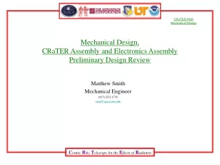
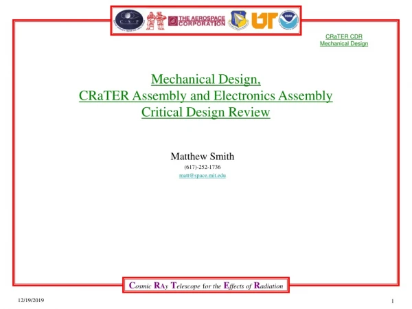
Mechanical Design, CRaTER Assembly and Electronics Assembly Critical Design Review. Matthew Smith (617)-252-1736 matt@space.mit.edu. Overview Assembly Description Mechanical Environments and Requirements Mechanical Design Details Near Term Tasks Back-up slides. Assembly Description.

E N D
Mechanical Design, CRaTER Assembly and Electronics AssemblyCritical Design Review Matthew Smith (617)-252-1736 matt@space.mit.edu
Overview Assembly Description Mechanical Environments and Requirements Mechanical Design Details Near Term Tasks Back-up slides
Assembly Description • Crater integrates two main sub-assemblies: The Telescope Assembly and The Electronics Assembly. • The Telescope Assembly is being designed and built by The Aerospace Corporation • The Analog Board is being designed by Aerospace. The Flight Analog Boards will be built by MIT • The Digital Board and Electronics Enclosure Assembly are being designed and built by MIT. • MIT will integrate the two sub-assemblies and perform all functional, environmental and acceptance testing. L13.5”x W9” x H 6” Weight 6.4Kgs max.
Overview Assembly Description Mechanical Environments and Requirements • Imposed • Internal Mechanical Design Details Near Term Tasks Back-up slides
Mechanical Environments - Imposed • From 431-RQMT-000012, Rev A, Environments Section 3.1. * Interpolated from Table 3-1 for CRaTER at 6.4Kgs.
Mechanical Environments, ImposedRandom Vibration Random Vibration Levels
Mechanical Environments,ImposedShock Environment Table 3-12 LRO/PAF Shock Response Spectrum
Mechanical Environments, ImposedShock Environment Table 3-13 Deployable Separation Mechanism Shock Response Spectrum
Mechanical Requirements and Verification • From 431-RQMT-000012, Rev A, Frequency Requirements Section 3.2.
Mechanical Requirements and Verification • From 431-RQMT-000012, Rev A, Verification Requirements Section 3.3.
Mechanical Requirements- Imposed Factors of Safety These are applied to the protoflight level testing
Mechanical Requirements - Imposed Test Factors Table 3-16
General Thermal Subsystem Requirements from 431-Spec-000091
Overview Assembly Description Mechanical Environments and Requirements • Imposed • Internal Mechanical Design Details Near Term Tasks Back-up slides
Internal Requirements for the Electronics Assembly • Derived Internal Mechanical Requirements for Electronics Assembly • Have adequate contact area (.5 in^2 min) to the spacecraft to support Thermal requirements. • Provide safe structure, within Factors of Safety specified, to support Telescope Assembly. • Provide for mounting 2 Circuit Card Assemblies. • The Analog Board and Digital Board must be separated by an aluminum plate. • Provide means to route cable from telescope to the Analog side of the Electronics Assembly to minimize noise. • Electrically isolate the Electronics Enclosure from the Telescope, yet provide sufficient thermal conductance path. • Electrical connector interface to the Spacecraft to be on one side of the Electronics Enclosure. • The interface connectors to be on the Digital side of the Electronics Enclosure (separate from the Analog side) • Provide GN2 purge interface inlet that routes to the telescope assembly and an outlet port at the digital board side of the internal volume. • Follow the octave rule for natural frequency of the PWAs to the Electronics Enclosure.
Overview Assembly Description Mechanical Environments and Requirements Mechanical Design Details Near Term Tasks Back-up slides
DESIGN DETAILS –Natural Frequencies • Natural Frequency Estimates • From SOLID WORKS cosmos package, 2005 • CRaTER Assembly • First frequency at 326 Hz (bottom cover) • Dominant Frequency at 1516 Hz (main assembly) • Analog Board- 195 Hz • Digital Board- 161 Hz • Bare E-box • First mode frequency is 1002 Hz at the side with connectors. • Third mode Frequency is 1239 Hz at the middle plate that holds the two Circuit Card Assemblies. • Top Cover- 284 Hz • Bottom Cover - 351 Hz • Telescope Assembly • First frequency- 1910 Hz • Dominant Frequency-
Random Vibration Loads • Load levels are dominated by random vibration spec. • For resonances in the Random Vibration Spec, Miles’ Equation shows 3 sigma loading on the order of 85-154 g • Assume Q=20
DESIGN DETAILSStress Margins, Electronics Assembly Pieces • Load levels are driven by random vibration spec • Factors of Safety used for corresponding material from 431-SPEC-000012. • Metals: 1.25 Yield, 1.4 Ultimate • Composite: 1.5 Ultimate • Margin of Safety = (Allowable Stress or Load)/(Applied Stress or Load x FS) – 1 Note 1. From SOLID WORKS, COSMOS excluding top and bottom covers in the model. All components have positive Margin of Safety
DESIGN DETAILSStress Margins, Hardware • Load levels are driven by random vibration spec • Factors of Safety used for corresponding material from 431-SPEC-000012. • Metals: 1.25 Yield, 1.4 Ultimate • Margin of Safety = (Allowable Stress or Load)/(Applied Stress or Load x FS) – 1
Mechanical Design DetailsSummary • The first fundamental frequency is estimated to be 327 Hz. • Not required to submit an FEM since our predicted first frequency is >75 Hz. • Meets stowage and deployed frequency requirements • Design meets all factors of safety. • All positive margins of safety. No Fracture Critical Items.
Material Properties • MIL-HDBK-5J • Efunda materials list via efunda.com 1 1 1 2
Mechanical Requirements and Verification Summary • We also meet all of our internal requirements: • Have adequate contact area (.5 in^2 min) to the spacecraft to support Thermal requirements. (min is .51 in^2) • Provide safe structure, within Factors of Safety specified, to support Telescope Assembly. • Provide for mounting 2 Circuit Card Assemblies. • The Analog Board and Digital Board must be separated by an aluminum plate. • The Analog Board to provide direct linear path for electronics from the telescope interface to the Digital Board interface to reduce noise. • Provide means to route cable from telescope to the Analog side of the Electronics Enclosure with minimizing noise. • Electrically isolate the Electronics Enclosure from the Telescope, yet provide sufficient thermal conductance path. • Provide adequate surface area for mounting electrical components. • Interface to the Spacecraft to be on one side of the Electronics Enclosure. • The interface connectors to be on the Digital side of the Electronics Enclosure (separate from the Analog side) • Provide GN2 purge interface inlet and outlet ports. • Follow the octave rule for natural frequency of the PWAs to the Electronics Enclosure.
Overview Assembly Description Mechanical Environments and Requirements • Imposed • Internal Mechanical Design Details Near Term Tasks Back-up slides
NEAR TERM TASKS FROM PDR • Update MICD to reflect latest configuration. • Released the MICD. • Further develop analysis on natural frequencies and stresses using SOLID WORKS and COSMOS on the complete CRaTER Assembly. • Completed all natural frequency and stress analysis. • Finalize interface between Telescope Assembly and Electronics Box Assembly. • Specify the electrical isolation material between the telescope and the E-Box. • Identify the GN2 purge system (mechanical interface to the spacecraft, internal flow, pressure measurements…) • Completed the design of purge system. • Complete the drawings for part and assembly fabrication. • Completed the fabrication drawings for the engineering unit. Assembly drawings are in process. • Flight drawings to be completed shortly after engineering unit is completed and tested. • Define attachment points and outline for thermal blankets. • To be completed after Engineering unit is finished.
NEAR TERM TASKS-Post CDR • Finish assembly of the Engineering Unit. • Complete the drawings of FLIGHT parts and assembly for fabrication. • Define attachment points and outline for thermal blankets. • Vibration testing of Engineering Unit. Generate procedures for Vibe tests.
Stress Margins Results • Load levels are dominated by random vibration spec. • Factors of Safety, FS, used for corresponding material (MEV 5.1) • Metals: 1.25 Yield, 1.4 Ultimate • Composite: 1.5 Ultimate • * Margin of Safety (MOS)= (Allowable Stress or Load)/(Applied Stress or Load x FS)-1
CRaTER Assembly Resonance • First Mode 326 Hz • Dominant Mode 1516 Hz
CRaTER Assembly Stresses • Using Miles Equation, Assume Q=20, • 3 sigma g loading= 154 g • Max Stress is 21,400 psi • MOS Y= 1.7 • MOS U= 1.8
Analog Board Resonance • First Mode 195 Hz
Analog Board Stresses • Using Miles Equation • Assume Q=20, • 3 sigma g loading= 93.9g • Max Stress is 15,212 psi • MOS Ult= 0.1
Digital Board Resonance • First frequency is 198 Hz.
Digital Board Stresses • Using Miles Equation • Assume Q=20, • 3 sigma g loading= 85.3 g • Max Stress is 8,646 psi • MOS Ult= 0.9
Top Cover Resonance • First Mode 288 Hz
Top Cover Stresses • Using Miles Equation, Assume Q=20, • 3 sigma g loading= 98 g • Material is aluminum • Max Stress is 4248 psi • MOS Y= 6.9 • MOS U= 6.1
Bottom Cover Frequency • First frequency is 351 Hz.
Bottom Cover Stresses • Using Miles Equation, • Assume Q=20, • 3 sigma g loading= 126 g • Max Stress is 23.8 kpsi • FOS= 3.1 • MOS Y= 1.5 • MOS U= 1.5